


3
7
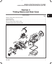
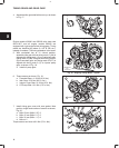
TIMING GEARS AND GEAR CASE
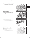
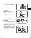
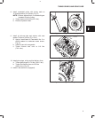
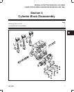
8. Install crankshaft pulley with timing mark at
12 o’clock position (#1 cylinder), Fig. 21.
NOTE: Be sure alignment pin in crankshaft gear
is seated in hole in pulley.
a. Torque screw to 88.0 Nm (65 ft. lbs.).
b. Remove flywheel holder.
Fig. 21 – Installing Crankshaft Pulley
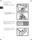
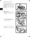
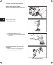
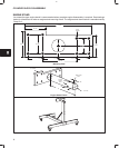
9. Install oil pick-up tube and strainer with new
gasket. Torque to 8.0 Nm (70 in. lbs.).
a. Apply a small bead of Permatex No. 2 or
similar sealant to crankcase areas shown,
Fig. 22.
b. Install oil pan with new gasket.
c. Torque screws and nuts to 8.0 Nm
(70 in. lbs.).
Fig. 22 – Installing Oil Pan
SEALANT
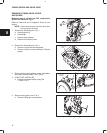
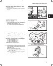
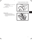
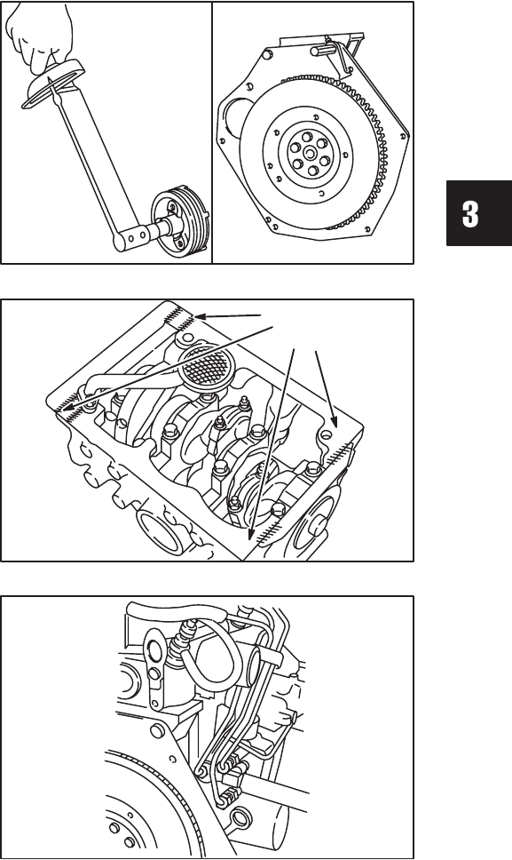
10. Install glow plugs, wiring and fuel delivery lines.
a. Torque glow plugs to 17.0 Nm (150 in. lbs.).
b. Torque fuel delivery lines to 25.0 Nm
(220 in. lbs.), Fig. 23.
11. Install V-belt and fan (if equipped).
Fig. 23 – Installing Fuel Delivery Lines