


9
6
CYLINDER BLOCK ASSEMBLY
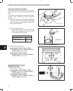
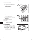
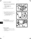
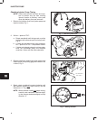
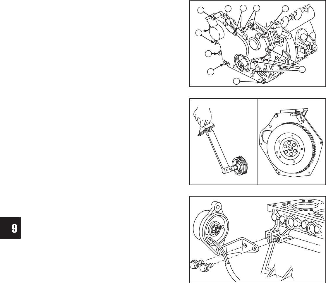
9. Install timing gear cover with new gasket. Note
position, length and number of screws as shown,
Fig. 18.
a. M6 x 55 mm (M6 x 2.5”): 3
b. M6 x 45 mm (M6 x 2.1”): 2
c. M6 x 30 mm (M6 x 1.1”): 9
d. M6 nut: 2
Torque screws and nuts to 8.0 Nm (70 in. lbs.).
Fig. 18 – Installing Timing Cover
B
C
A
A
B
D
C
D
C
C
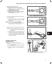
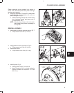
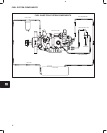
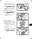
10. Install crankshaft pulley with timing mark at
12 o’clock position (#1 cylinder), Fig. 19.
NOTE: Be sure alignment pin in crankshaft gear
is seated in hole in pulley.
a. Torque screw to 88.0 Nm (65 ft. lbs.).
b. Remove flywheel holder.
Fig. 19 – Installing Pulley
FLYWHEEL HOLDER
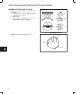
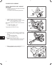
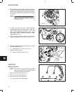
INSTALL ALTERNATOR
1. Install alternator bracket and alternator, Fig. 20.
a. Torque screws to 19.0 Nm (170 in. lbs.).
Fig. 20 – Install Alternator
GENERAL ASSEMBLY
1. Lubricate tappets with engine oil and install in
cylinder block.
2. See Section 2 for installation of cylinder head and
related components.