


12
8
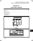
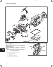
LUBRICATION SYSTEM
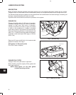
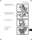
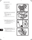
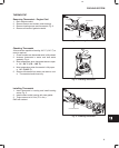
6. Torque screws as shown, Fig. 19.
a. Camshaft gear:
41.0 Nm (30 ft. lbs.)
b. Idler gear:
25.0 Nm (220 in. lbs.)
c. Injector pump gear:
61.0 Nm (45 ft. lbs.)
d. Oil pump gear:
19.0 Nm (170 in. lbs.)
Fig. 19 – Torque Screws
C
D
B
A
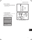
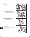
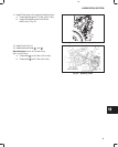
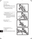
7. Install timing gear cover with new gasket. Note
position, length and number of screws as shown,
Fig. 20.
a. M6 x 55 mm (M6 x 2.5”): 3
b. M6 x 45 mm (M6 x 2.1”): 2
c. M6 x 30 mm (M6 x 1.1”): 9
d. M6 nut: 2
8. Torque screws and nuts to 8.0 Nm (70 in. lbs.).
Fig. 20 – Installing Timing Gear Cover
B
C
A
A
B
D
C
D
C
C
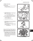
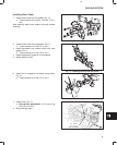
9. Install crankshaft pulley with timing mark at
12 o’clock position (#1 cylinder), Fig. 21.
NOTE: Be sure alignment pin in crankshaft gear
is seated in hole in pulley.
a. Torque screw to 88.0 Nm (65 ft. lbs.).
b. Remove flywheel holder.
Fig. 21 – Installing Crankshaft Pulley
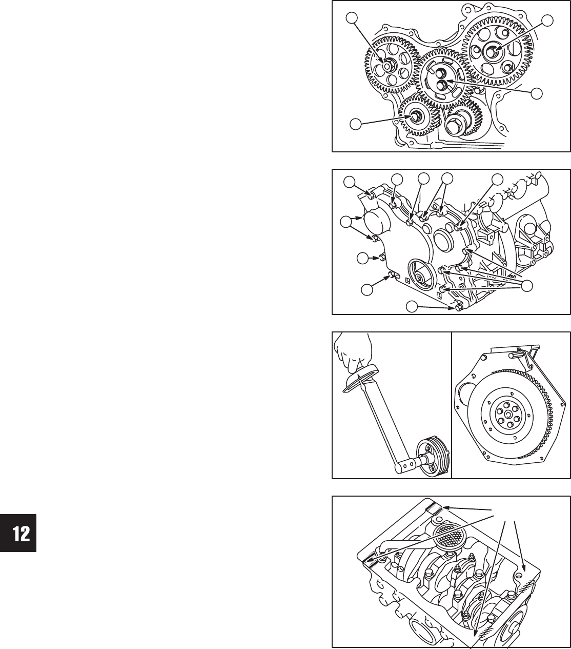
10. Install oil pick-up tube and strainer with new
gasket. Torque to 8.0 Nm (70 in. lbs.).
a. Apply a small bead of Permatex No. 2 or
similar sealant to crankcase areas shown,
Fig. 22.
b. Install oil pan with new gasket.
c. Torque screws and nuts to 8.0 Nm (70 in. lbs.).
Fig. 22 – Installing Oil Pan
SEALANT