


78/83/90 Series Horizontal Shaft Engines
88
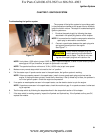
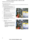
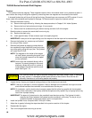
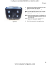
Flywheel
The flywheel holds the magnets. These magnets induce a field in the module which in turn produces a spark. It
also controls the timing of the ignition system by controlling when the magnets are introduced to the module.
A sheared flywheel key will throw off the ignition timing. Sheared keys are uncommon on MTD engines. If one is
found, check the crankshaft and flywheel for damage. To Remove and/or inspect the flywheel and key:
1. Remove the blower housing.
1a. Remove the engine shroud by following the steps procedures in Chapter 3: Air Intake Systems
1b. Remove the front fuel tank shroud using a 10 mm wrench.
1c. Remove the five screws securing the blower housing and slide it off of the engine.
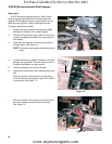
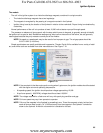
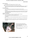
2. Block the piston to prevent the crank shaft from turning by:
2a. Remove the spark plug.
2b. Insert approximately 3.5 feet of starter rope in the spark plug hole.
IMPORTANT: Leave part of the rope sticking out of the engine so that the rope can be removed later.
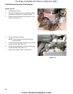
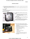
3. Remove the flywheel nut, starter cup and flywheel
fan using a 23mm wrench.
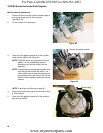
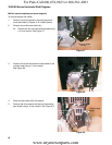
4. Remove the flywheel by applying a sharp blow to
the crankshaft using a brass drift punch and a ham
-
mer while gently prying with a pry bar. The flywheel
will loosen then lift it off.
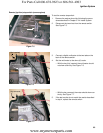
NOTE: The magnets on the inside of the magnet
will hold it down, preventing the typical “pop”
when the flywheel loosens from the tapper
on the crankshaft.
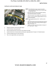
NOTE: Never strike the crankshaft directly with a
hammer. To prevent damage to the crank
-
shaft use a brass drift punch or a piece of
wood between the hammer and the crank
-
shaft. See Figure 7.14.
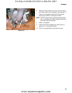
5. Inspect the key, keyway, and tapered mating surfaces of the flywheel and crankshaft.
NOTE: If the key is damaged, it must be replaced. If there is damage to the crankshaft, the engine must be
short blocked because the crankshaft is not available as a service part.
NOTE: On installation, confirm that the key is properly seated (the flat of the key parallel with the threaded
section of the crankshaft) in the keyway, and that the tapers are fully seated. Key or keyway failure may
result from improper seating.
IMPORTANT: The tapers in flywheel and on the crankshaft must be clean and dry. The flywheel is held in
place by the friction between the flywheel and the crankshaft, not the key. The key is only to
guide the flywheel to the proper position until it is torqued down.
6. Install the flywheel nut to a torque of 66-81 ft-lbs (90-110Nm).
7. Adjust the air gap by following the steps described in the previous section of this chapter.
8. Reassemble the engine.
9. Test run the engine before returning to service.
Figure 7.14
Brass punch
! CAUTION! CAUTION
If the flywheel shows any signs of physical damage such as cracks, broken vanes, or damaged
key-way, replace it. A damaged flywheel poses a threat of burst failure. Burst failures are
extremely hazardous to surrounding people and property.
For Parts Call 606-678-9623 or 606-561-4983
www.mymowerparts.com