


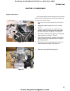

Crankshaft, piston and connecting rod
105
The exact procedure a technician uses to disassemble an engine depends on the type of repairs needed. This
chapter is written as a set of procedures that should provide the user with sufficient information to complete any fea
-
sible repair to the engine short block assembly.
The instructions are written with the assumption that the engine has been removed from the equipment. These
are bench work instructions.
.
1. Drain and save the oil from the engine by following the steps described in Chapter 1: Introduction.
2. Remove the fuel tank by following the steps described in Chapter 4: Fuel system and Governor.
3. Remove the air intake and carburetor by following the steps described in Chapter 3: Air Intake Systems.
4. Remove the starter by following the steps described in Chapter 6: Starter and Charging Systems.
5. Remove the flywheel and ignition module by following the steps described in Chapter 7: Ignition system.
6. Remove the muffler by following the steps described in Chapter 8: Exhaust.
7. Remove the cylinder head by following the steps described in Chapter 9: Cylinder Head.
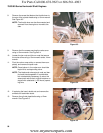
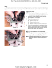
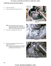
8. Remove the dipstick tube.
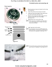
9. Remove the crank case cover bolts using a 12mm wrench.
10. Carefully slide the crank case cover off of the crank shaft.
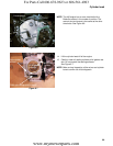
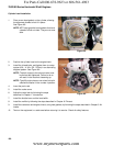
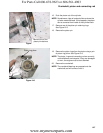
11. Align the timing marks to allow easier removal of the cam shaft and to help protect the compression relief from
damage.
See Figure 10.1.
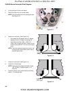
Figure 10.1
Timing marks
CHAPTER 10: CRANKSHAFT, PISTON AND CONNECTING ROD
For Parts Call 606-678-9623 or 606-561-4983
www.mymowerparts.com