


Crankshaft, piston and connecting rod
111
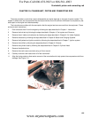
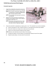
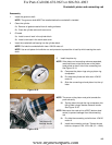
Connecting rod inspection
1. Inspect the connecting rod for cracks or any signs of
damage.
2. Install the rod cap and tighten to a torque of 106 - 124
in-lbs (12 - 14Nm).
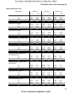
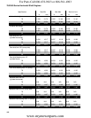
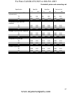
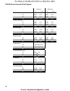
3. Measure the inside diameter of the connecting rod at
both ends and compare the measurements to those
listed in the chart at the end of this chapter.
See Figure 10.14.
NOTE: Take two measurements 90 degrees apart. This
will check the roundness of the connecting rod
bearing surfaces.
NOTE: Connecting rods are not available as service parts.
If the connecting rod is bad, the engine must be
short blocked.
4. Take the crank pin and piston pin measurements and subtract them from the connecting rod measurements to
get the connecting rod to journal running clearance and the piston pin to connecting rod running clearance.
Compare that number to the one listed in the chart at the end of this chapter.
NOTE: Plasti-gauge can be used to measure the connecting rod to journal running clearance, but it is very
technique sensitive and it is not as reliable as the method described above.
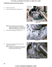
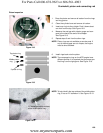
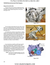
Cylinder inspection
1. Clean and inspect the cylinder, inside and out.
NOTE: If there is any sign of damage, especially cracked
cooling fins, short block the engine.
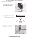
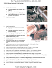
NOTE: Take two measurements of the cylinder bore 90
degrees apart at the top, bottom and middle of the
cylinder.
See Figure 10.15.
NOTE: The measurements can be made using telescop-
ing gauges, inside micrometers or dial indicating
bore gauge.
2. Compare the measurements to those that are listed
in the chart at the end of the chapter.
• The bore should not be worn too large
• The bore should not be tapered.
• The bore should be round, not oval shaped.
3. Inspect the cylinder cross hatch.
NOTE: The cross hatch is important because it helps hold oil on the cylinder walls.
NOTE: If the cross hatch is polished off, that is a sign of dirt ingestion. The cylinder can not be re-honed
because replacement piston rings are not available. The engine must be short blocked.
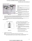
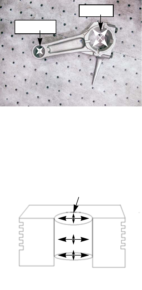
Figure 10.14
Measure at
right angles
Measure at
right angles
Figure 10.15
Measure the cylinder bore
For Parts Call 606-678-9623 or 606-561-4983
www.mymowerparts.com