


FUEL SYSTEM AND GOVERNOR
53
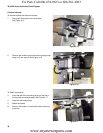
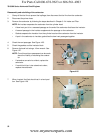
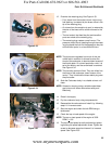
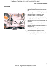
8. Remove the pin that the float hinges on to remove
the float.
NOTE: The float is not adjustable. Spring tension against
the float valve begins to build from the horizontal
position, putting progressively more pressure
between the tip of the valve and the seat.
See Figure 4.28.
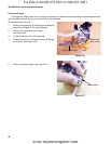
NOTE: Because the float valve is crucial to the functioning
of the carburetor, and the viton tip of the valve is
subject to wear, technicians should replace the
valve and spring any time the carburetor is disas
-
sembled for cleaning.
• A square cross-section gasket seals the bowl to
the body of the carburetor.
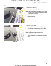
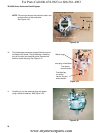
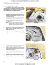
9. Remove the main jet using a narrow-shank straight
blade screwdriver.
See Figure 4.29.
NOTE: Fuel enters the central column through a port
about 1/2” (1cm) from the bottom, to help prevent
the ingress of any residue in the bottom of the
bowl.
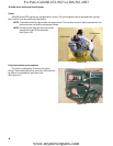
NOTE: The orifice in the main jet meters fuel into the cen-
tral column.
NOTE: Air from the main jet emulsion port enters the cen-
tral column near the top, then gets bubbled
through the emulsion tube into the metered fuel
flow to promote atomization.
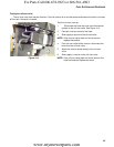
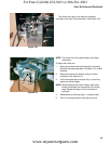
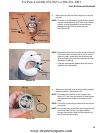
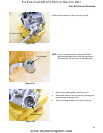
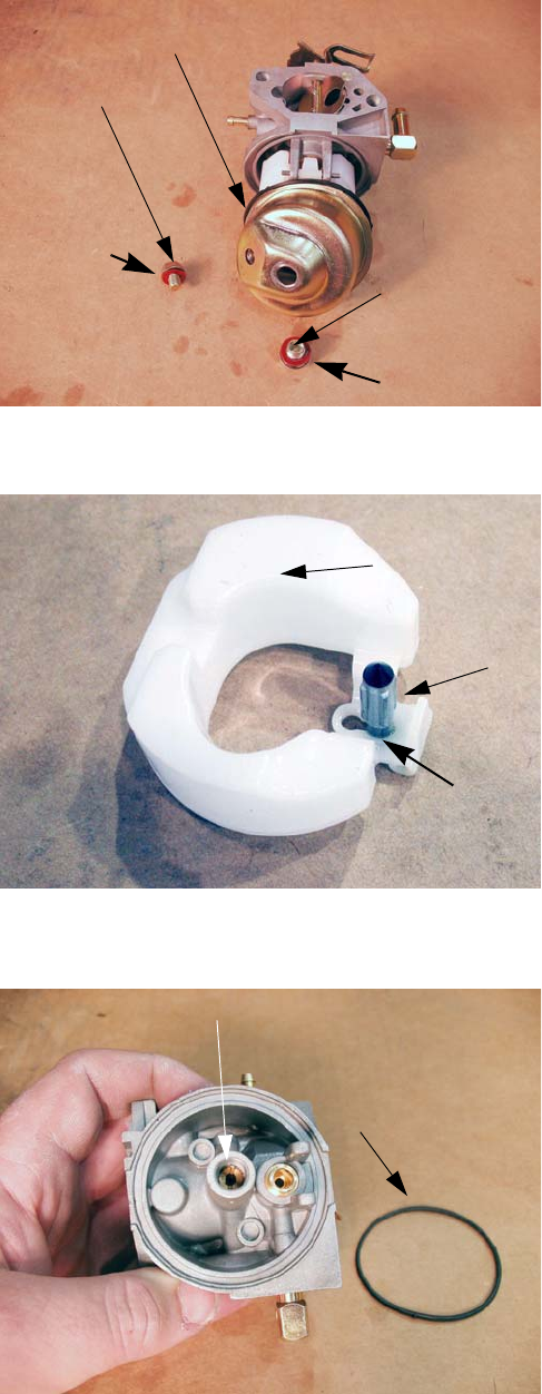
Figure 4.27
Float bowl
Drain bolt
Flat fiber
gasket
Bowl bolt
with recess in
head for O-ring
Gasket seal
Figure 4.28
Float
Compression
spring
Float valve
Figure 4.29
Main jet
Bowl gasket
For Parts Call 606-678-9623 or 606-561-4983
www.mymowerparts.com