


78/83/90 Series Horizontal Shaft Engines
60
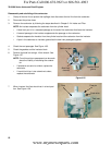
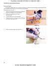
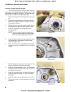
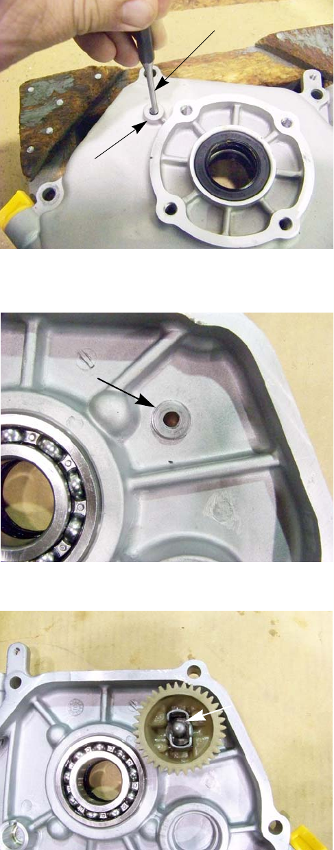
Governor cup and the governor gear
The Governor gear and cup are located inside the
crankcase cover. The flyweights and the governor cup are
inter locked on this family of engines. The governor gear
and cup are serviced as a complete assembly.
1. Remove the engine from the equipment that it pow-
ers.
2. Remove the crank case cover from the engine by
following the steps described in Chapter 10: Cam,
Crankshaft and Piston.
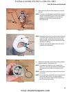
3. Position the crank case cover over an open vise so
that the governor gear can pass through its jaws.
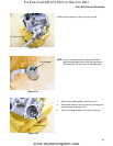
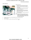
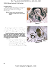
4. Drive out the governor pin using a pin punch.
See Figure 4.44.
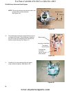
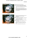
NOTE: There is a washer between the governor
cup and the crank case cover. this washer
will fall out when the governor comes out.
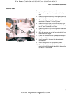
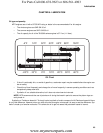
5. Install the governor gear and cup assembly by plac-
ing the washer on the inside of the crank case
cover.
See Figure 4.45.
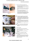
6. Apply a small amount of releasable thread locking
compound such as Loctite® 242 (blue) to the gover
-
nor pin.
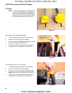
7. Position the governor gear and cup assembly with
the pin in the hole in the crank case cover.
8. By gently striking the governor cup, drive the gover-
nor pin into the crank case cover until it is flush with
the out side of the cover.
9. Install the crank case cover by following the proce-
dures described in Chapter 10: Cam, Crankshaft
and Piston.
10. Install the engine onto the equipment it came off of.
11. Test run the engine in a safe area before returning it
to service.
Figure 4.44
Governor pin
Pin punch
Figure 4.45
Washer
Figure 4.46
Governor cup
For Parts Call 606-678-9623 or 606-561-4983
www.mymowerparts.com