


FUEL SYSTEM AND GOVERNOR
55
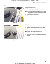
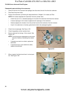
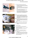
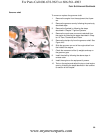
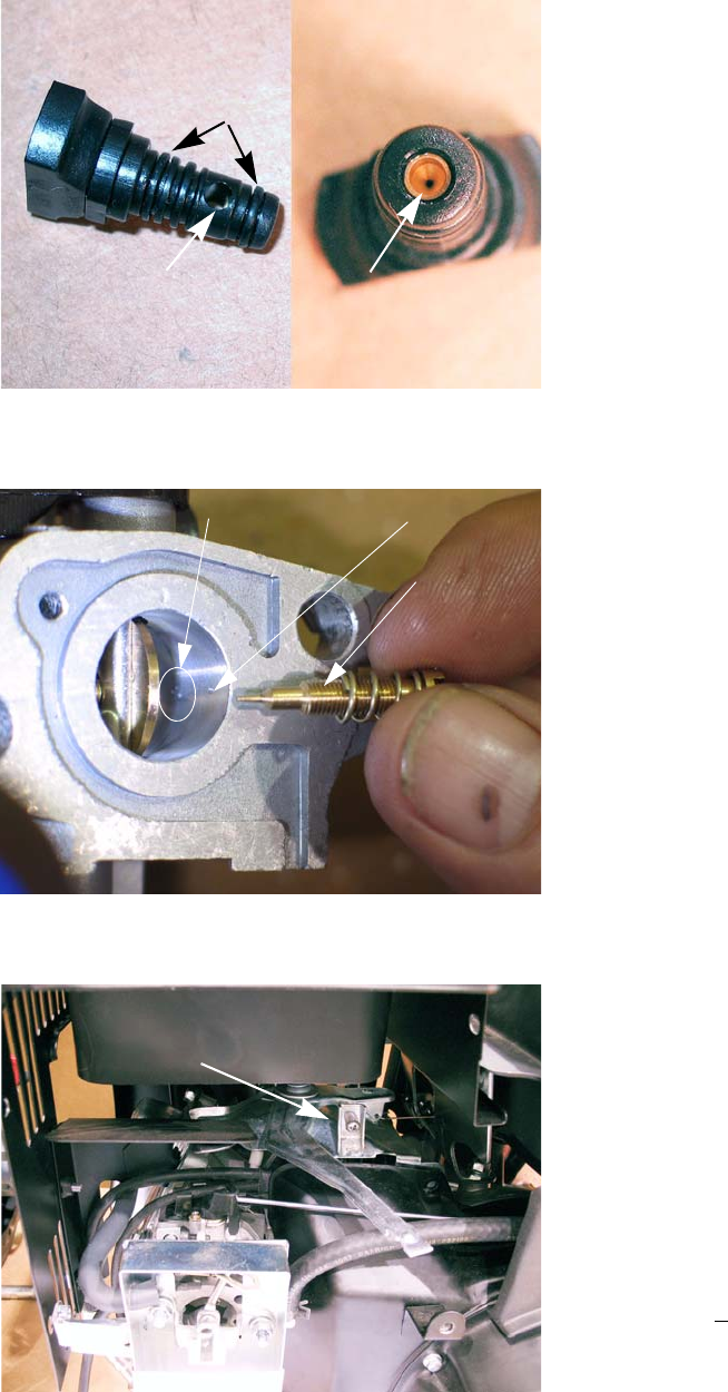
12. Examine the metering plug: See Figure 4.33.
• Fuel, drawn from the central column via the long
fuel feed leg, is metered by the brass orifice in the
tip of the metering plug.
• Air, drawn from the emulsion air port, is metered by
the size of the brass orifice at the entrance to the
port.
• The fuel and air that feed the pilot and transition
ports are mixed at the metering plug.
• The metering plug creates a small venturi. The
pressure drop of the air passing through the meter
-
ing plug draws the fuel into the passage to the pilot
and transition ports, in an emulsified mixture.
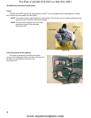
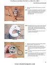
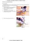
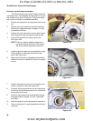
NOTE: The pilot screw regulates how much of this pre-
mixed fuel/air emulsion is allowed to enter the
throat of the carburetor, to atomize down-stream of
the throttle plate. On current production units, it is
set at the factory and the screw head is removed.
See Figure 4.34.
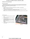
NOTE: The transition ports are fixed. They are drilled into
the throat of the carburetor, down-stream of the
venturi. They lie behind the brass welch plug near
the pilot screw.
13. Soak the Carburetor body in a suitable solvent until
clean.
NOTE: Ultrasonic cleaning using a suitable water/deter-
gent mixture will clean carburetors safely and
effectively.
14. Rinse it thoroughly.
15. Dry the carburetor body using compressed air.
16. Reassemble the carburetor and install it by following
steps 1-8 in reverse order.
17. Start the engine and check the idle RPM using a
tachometer.
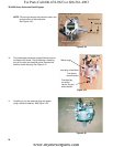
18. Check the top no load speed of the engine.
NOTE: The top no-load speed of the engine is 3500
RPM’s
+ 100.
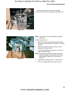
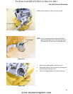
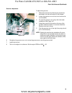
19. The top no-load speed is easily adjusted by tighten-
ing/loosing the speed adjustment screw. Tighten the
screw to decrease speed and loosen it to increase
speed.
See Figure 4.35.
Figure 4.33
Air passage
O-rings
End view
Fuel metering orifice
Figure 4.34
Transition ports Pilot port
Pilot screw
(before head
is removed)
Figure 4.35
Adjustment screw
For Parts Call 606-678-9623 or 606-561-4983
www.mymowerparts.com