


TD - Series
- 40 -
TD Series Digital Solid State Soft Starter 48 - 1250A
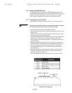
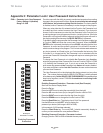
8.4 Replacing the Printed Circuit Board Assembly
The printed circuit board assembly is not intended to be field
repaired. If a board is faulty, the entire assembly should be
replaced using the following procedure:
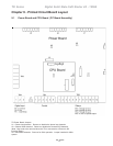
(See Chapter 9 for the printed board assembly layout.)
• Remove three phase power and control power from the unit and
lock out.
• Remove plugs and tag plugs with connector numbers.
• Remove control wires from terminals and tag wires with terminal
numbers.
• Remove the mounting screws.
• Remove the old printed circuit board assembly.
• Mount the new printed circuit board assembly.
• Install the mounting screws.
• Install the control wires onto correct terminals per tag sequence.
• Install the plugs.
• Apply power to the unit and test.
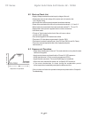
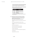
uses the spin washer gauge, verify that the washer spins freely after
clamping. Once proper force is reached make sure that the SCR pucks
are securely held between the heatsinks and aligned evenly.
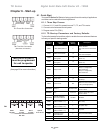
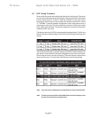
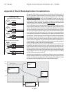
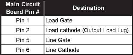
• Replace any lugs, MOVs, snubbers, power straps, printed circuit
boards and associated wiring that was removed in step 4. Use the
following chart to verify wiring of J5, J6 and J7:
• After verifying that all wiring is correctly connected, test the SCR
and then test the unit.