


TD - Series
- 39 -
TD Series Digital Solid State Soft Starter 48 - 1250A
8.3.2 Changing a Hockey Puck Type SCR
• Remove both line and control power from unit, tag and lock out.
Failure to remove both line and control power before starting this
procedure may cause personal injury or death.
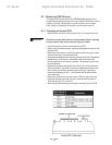
• TOSHIBA uses two types of clamps with gauges for reading the
amount of force on the device. The first type of force gauge uses a
spin washer. When the proper force is applied, the washer will be
free to spin. The second type of gauge uses a step indicator on the
end of the lever. Before proceeding, note the type of clamp used
and, if the clamp has a step indicator, document the position of the
indicator before removing the clamp to facilitate proper mounting of
the new SCR device.
• Label the location of the wires connected to the SCR.
• Remove any lugs, snubbers, printed circuit boards (refer to section
8.4) and associated wiring that may get in the way of reaching the
faulty SCR. Document the location and wiring of all parts before
removing them to facilitate the reinstallation of the devices later.
• Document the position of the indicator on the SCR clamp. Then remove
the top clamp holding the SCR stack together. Remove the top
heatsink. Use extreme caution when handling the heat sink so it does
not become dented or damaged.
• Remove the faulty SCR device, noting the direction in which the
SCR is oriented. The new SCR puck must be inserted in the same
direction.
• Make sure the SCR mounting surface, tools, and hands are clean
and free from dirt, nicks, and scratches. Do not sand or scrape SCR
mounting surface. If necessary, super fine Scotch Brite pads can be
used to clean the heatsink before installing the new SCR.
• Apply a thin (3 mil thick) layer of thermal grease uniformly along
both sides of the SCR. Spread the grease to cover the entire surface
of both sides of the SCR in a manner that minimizes air pockets.
The grease must be free of contamination.
• Locate the centering pin in the bottom and top of the heatsink and
center it in the SCR hole (making sure that the SCR is pointed in the
same direction as the SCR that was removed in step 6). Locate the
centering pin in the top heatsink and center it in the SCR hole.
If center pin is not placed correctly it will damage the SCR and
the heat sink.
Hand tighten the clamps evenly so that the same number of threads
appear at both ends of the U-clamp. Tighten the clamp 1/4 turn at a
time alternating sides of the U-clamp until the correct force is reached.
Check the gauge or spin washer every time the clamp nuts are tightened
1/4 turn to ensure that the SCR is not over torqued. The gauge reading
should be similar to the initial reading taken in step 2. If the clamp
WARNING