


TD - Series
- 37 -
TD Series Digital Solid State Soft Starter 48 - 1250A
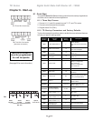
8.2 SCR Testing Procedure
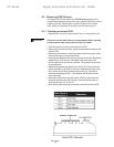
Remove both line power and control power from the unit and lock out. Disconnect
any two motor load leads and any two line leads. Disconnect the SCR connections
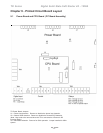
to main control board J5, J6 and J7. Refer the Chapter 9 for the main control
board layout. Note the type of color coding of the wires connected to J5, J6 and
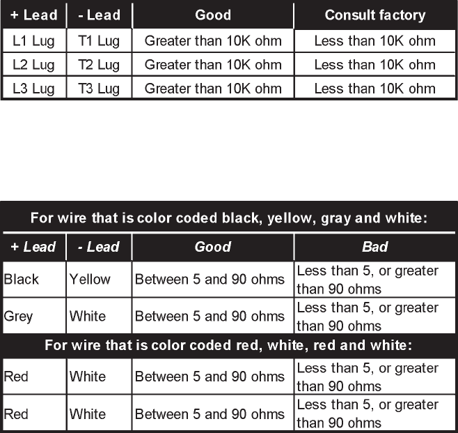
J7. TOSHIBA™ uses two possible configurations. Both configurations have 4
wires going to each plug. The first configuration consists of 4 wires color coded
black, yellow, grey and white. The second configuration consists of 4 wires color
coded red, white, red, white.
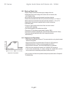
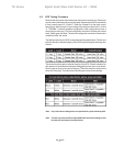
The testing procedure for SCRs is comprised of two separate tests. The first one
tests the anode to cathode integrity of the SCR by performing the following ohm
checks:
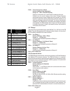
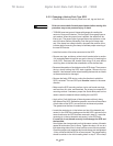
The second tests the gate to cathode integrity of the SCR. Place the leads of an
ohm meter into the receptacle that was unplugged from the main circuit board.
Ohm the pair of wires on one end of the plug. Then ohm the pair of wires on the
other end of the plug. The chart below indicates good versus bad readings.
Note: If any of the above readings are out of specifications, replace the faulty SCR.
Note: The best way to test an SCR is with an SCR Tester and look for leakage current
less than the manufacturer specified values.