


F-2200 Series Vortex Flow Meter Installation and Operation Guide • Revised 12/08
9
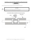
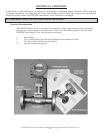
1.4 ADDITIONAL REQUIRED MATERIALS
Installer is responsible for providing suitable anges and fasteners to connect the meter to the
process piping. In addition, most installations will also require one reducer, one expander, pipe
supports and a suf cient length of straight pipe (pipe diameter = meter size) to meet the installation
requirements outlined in this manual. Use of an optional ow recti er may be required in cases
where the available space is not suf cient to allow for proper upstream straight pipe run.
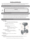
1.5 WORKING ENVIRONMENT
ONICON F-2000 series vortex ow meters are designed for use in industrial environments that are
free of corrosive liquids, fumes and excessive vibration. Do not expose the ow meter electronics
enclosure to direct sunlight. Install a sunshade if necessary. Do not expose the ow meter to intense
vibration. If necessary, provide additional support to the pipeline, at the meter location, to minimize
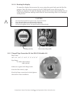
vibration. The rotating design of the electronics enclosure makes it easier to connect the power and
signal cables to the terminals in the rear of the enclosure. Rotate the enclosures as necessary before
installing the meter.
The ambient operating temperature range is 0° to 132° F.
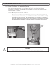
1.6 SERIAL NUMBER
The serial number for your F-2000 series vortex ow meter is located on the metal identi cation
plate mounted on the side of the electronics enclosure. Please have this number available whenever
you contact ONICON for assistance.