


F-2200 Series Vortex Flow Meter Installation and Operation Guide • Revised 12/08
5
TABLE OF CONTENTS
1.0 INTRODUCTION ..............................................................................................................7
1.1 Purpose of This Guide .............................................................................................. 7
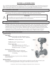
1.2 Principal of Operation .............................................................................................. 7
1.3 Features and Speci cations ...................................................................................... 7
1.4 Additional Required Materials ................................................................................. 9
1.5 Working Environment ............................................................................................... 9
1.6 Serial Number ........................................................................................................... 9
2.0 UNPACKING .................................................................................................................... 10
2.1 Checking That You Have Received Everything ..................................................... 10
3.0 INSTALLATION INFORMATION ................................................................................... 11
3.1 Site Selection ........................................................................................................... 11
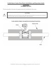
3.1.1 Flow direction and meter position .............................................................. 11
3.1.2 Maximum allowable difference between inside of meter body and
the connecting pipe ...................................................................................... 12
3.1.3 Straight, unimpeded inlet and outlet runs .................................................. 13
3.1.4 Minimizing pipe vibration ........................................................................... 14
3.1.5 Locating the meter in a pipeline that runs parallel to a wall ..................... 14
3.1.6 State of medium ........................................................................................... 14
3.1.6.1 Liquid Applications ..................................................................... 14
3.1.6.2 Steam or compressed gas applications ........................................ 14
3.2 Mechanical Installation .......................................................................................... 15
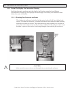
3.2.1 Orient the display for convenient viewing ................................................. 15
3.2.1.1 Liquid applications ...................................................................... 15
3.2.1.2 Steam or compressed gas applications ........................................ 16
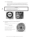
3.2.2 Flanged type connections to ANSI B16.5 (Schedule 40) ............................ 16
3.2.3 Temperature Measurements ......................................................................... 17
3.3 Wiring Terminations ............................................................................................... 17
4.0 START-UP & TROUBLESHOOTING .............................................................................. 18
4.1 Start Up .................................................................................................................... 18
4.2 Measurement Mode ................................................................................................. 18
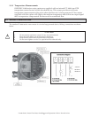
4.3 Operating the Display ............................................................................................. 19
4.4 Error Handling ......................................................................................................... 20
4.5 Troubleshooting Hints............................................................................................. 21
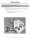
5.0 FLOW STRAIGHTENER CATALOG SHEET .................................................................. 22