


F-2200 Series Vortex Flow Meter Installation and Operation Guide • Revised 12/08
18
SECTION 4.0: START UP AND TROUBLESHOOTING
4.1 START UP
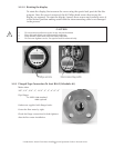
When the power is applied to the F-2000 series vortex meter, alphanumeric characters will appear
on the display. Initially, the meter will operate in a “TEST” mode where self diagnostic checks are
performed on the pre-ampli er and sensor circuits. Following this, con guration data is loaded
from the non-volatile memory and the program advances to the measurement mode.
!
i
i
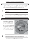
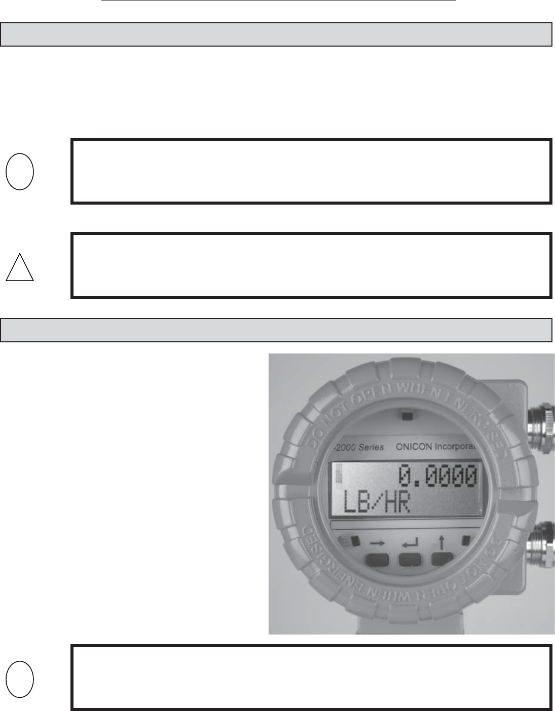
4.2 MEASUREMENT MODE
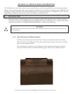
In the measurement mode, the display
indicates real-time ow, temperature and/
or pressure data in the appropriate units.
The top line of the display indicates the
current measured value. The second line
of the display indicates the programmed
units of measurement.
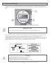
There are two options for displaying data in
the measurement mode. The display may
be set to automatically scroll through each
menu page or it may be set to manually step
through the menu pages using the up arrow
key to advance each page. Displays operating
in the cyclic mode will advance through
each page every 6 seconds.
IMPORTANT NOTE
The meter should be installed and powered for at least 15 minutes before media is allowed to ow
through the meter.
CAUTION
Flow velocity through the meter should be increased gradually until full ow is achieved.
IMPORTANT NOTE
When measuring steam ow, condensate may form on the cool surfaces of the meter and piping
system when the system is started up for the rst time (causing faulty measurement).