


F-2200 Series Vortex Flow Meter Installation and Operation Guide • Revised 12/08
21
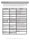
REPORTED
PROBLEM
POSSIBLE
SOLUTIONS
A non-zero fl ow indi-
cated when no actual
fl ow is in the pipe.
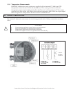
• Mains interference due to improper Earth ground connection. The protective
Earth PE terminal should be properly grounded (see page 17).
• Excessive mechanical vibration in the pipe. If so, support the pipeline near the
meter perpendicular to both the axis of the pipe and the axis of the shedder
bar.
• This problem may also be solved by reducing the factory set gain. (Contact
ONICON for assistance.)
NOTE: By reducing the gain, the minimum measurable fl ow rate will go up
by the factor which is approximately equal to the square root of the gains
(odd gains new gain). If the minimum fl ow with reduced gain is above the
minimum fl ow which is required to be measured, then reducing the gain is
not the permanent solution. Then the installaion should be corrected and
also the vibrations should be eliminated.
“CHECK INST.” error
is displayed when no
fl ow is in the pipe.
The display should normally indicate 0.0 fl ow rate, LOW FLOW or LOW SIGNAL
when there is no fl ow in the pipe. The additional CHECK INSTALL error (fl ow
rate = 0.0 or some steady or fl uctuating value) is an indication of:
• Improper/inadequate earthing
• Excessive pipe vibration
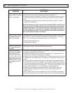
Flow rate inidcated is
0.0 even with fl ow in
the pipe.
• The vortex sensor cable is disconnected or is not properly connected.
• Flow sensor is faulty. Contact ONICON for assistance.
The fl ow indicated
responds to changes
in the fl ow but the
indicated value does
not correspond to the
actual fl ow rate. Also
“CHECK INST.” Error
may appear intermit-
tently.
• The meter is not properly centered on the pipeline. The axis of the meter bore
should be aligned with that of the pipe.
• Gaskets at the meter are protruding into the pipe bore. The gaskets must not
project into the effective cross-section of the pipe.
• Irregularities on the surface of the pipe bore. The pipe bore should be free from
irregularities at the welded joints, dirt, deposits and excessive surface rough-
ness.
• The Vortex signal is distorted due to a bi-phase medium. Bi-phase media are
not permitted. Use a moisture separator for wet steam applications to remove
the moisture droplets from the steam. Use suitable fi lters in gas applications to
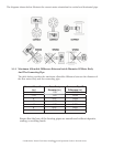
remove solid particles from the fl owing gas. • Incorrect angular position of the
meter. Refer to Section 3.1.1 for the allowable mounting positions.
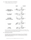
• Insuffi cient upstream/downstream pipe lengths. Check that the upstream/
downstream pipe lengths are of the correct minimum length as given in
Section 3.1.3.
• Error in meter factor K-Factor programming. Contact ONICON for assistance.
• Check that the fl ow direction and the direction arrow on the meter body agree.
4.5 TROUBLESHOOTING HINTS