


F-2200 Series Vortex Flow Meter Installation and Operation Guide • Revised 12/08
14
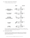
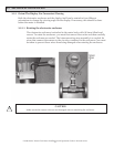
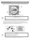
3.1.5 Locating The Meter In A Pipline That Runs Parallel To A Wall
Wherever possible, the distance between the pipe centerline and the wall should be greater
than 20”. This will allow for access to the electronics enclosure compartment where wire
terminations are made. If adequate space is not available, rst connect all the cables to the
terminals in the connection compartment (power supply and outputs) and then run the wires
to an intermediate junction box (also see Section 3.2) before installing the meter.
3.1.6 State Of Medium
In all cases the meter requires a single-phase ow for proper operation. Liquid droplets in
the gas or vapor, solid particles in the gas or liquid and gas bubbles in the liquid are not
permitted.
3.1.6.1 Liquid Applications
When operating with liquids, the meter requires a minimum downstream pressure
to prevent cavitation. The formula used to determine the minimum downstream
pressure is as follows:
Pds(bar_g) > =(2.9*DP) + (1.3*Ps)-1.013
Where DP=pressure drop of the meter, in Bar, as determined by the ONICON sizing
program and Ps=saturation pressure, in Bar, at the operating temperature.
For any uid, a lter or strainer may be used to remove the solid particles. This is
especially important for meter sizes below 1” where a lter or a strainer is required.
3.1.6.2 Steam Or Compressed Gas Applications
In case of steam or compressed gas, a moisture separator should be used 50D
upstream of the meter if the dryness fraction is less than 95%.
i
IMPORTANT NOTE
Steam quality will affect the accuracy of the measurement. It is strongly recommended that a moisture
separator be installed upstream of the inlet straight pipe run for anything less than 95% dry steam.