


F-2200 Series Vortex Flow Meter Installation and Operation Guide • Revised 12/08
19
4.3 OPERATING THE DISPLAY
Please read the entire procedure before proceeding. Wiring diagrams are located in the Appendix. A
worksheet for checking off the following steps and recording measured values is located on the next
page.
i
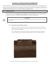
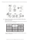
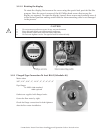
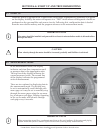
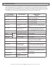
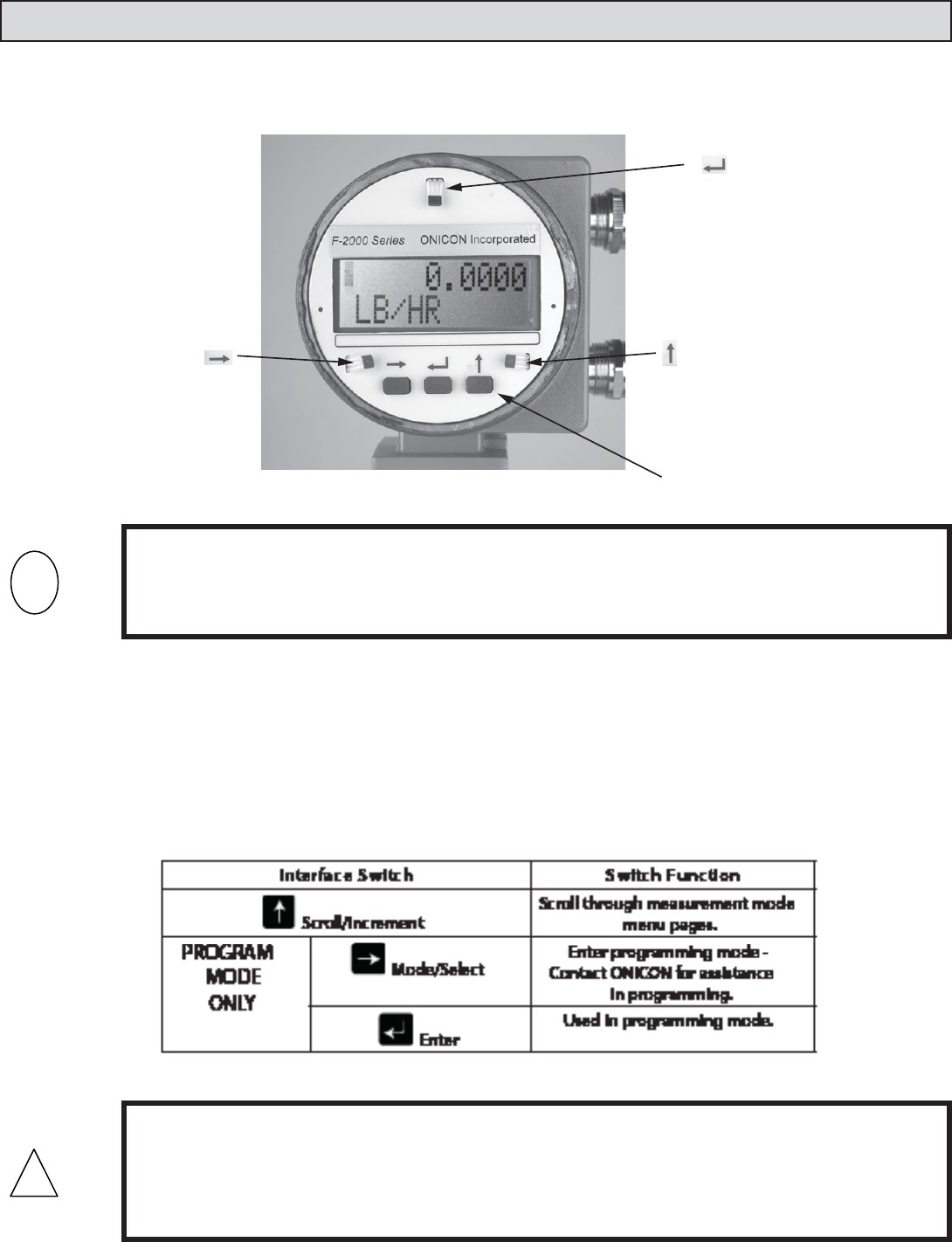
There are 3 user interface switches located immediately below the display. Each switch performs a
separate function. The table below describes the function of each switch. There are also 3
corresponding Hall Effect switches that perform the same functions. The Hall Effect switches may be
activated without removing the display cover, using the magnet provided with the meter. Place the
magnet against the cover in proximity to the Hall Effect switch to activate.
!
IMPORTANT NOTE
Do not attempt to enter the program mode without rst contacting ONICON service.
CAUTION
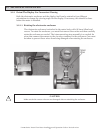
• Do not remove enclosure covers in any wet environment.
• Keep dirt and debris out of electronics enclosure.
• Keep threads lubricated (silicone based lubricant).
• Do not over tighten covers. Use special tool for removal only.
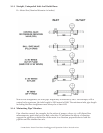
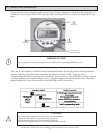
key Hall
Eect Switch
key Hall
Eect Switch
key Hall
Eect Switch
Display page scroll
(measurement mode)