


F-2200 Series Vortex Flow Meter Installation and Operation Guide • Revised 12/08
16
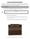
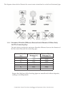
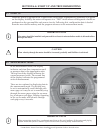
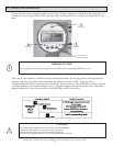
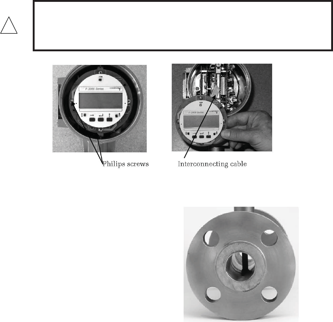
3.2.1.2 Rotating the display
To rotate the display, rst unscrew the cover using the special tool provided for this
purpose. Once the cover is removed, the (4) Philips head screws that secure the
display are exposed. To rotate the display, remove these screws and carefully move it
to the desired position making certain that the interconnecting cable is not damaged
in the process.
!
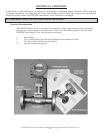
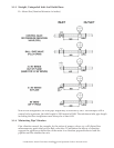
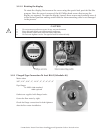
3.2.2 Flanged-Type Connection To Ansi B16.5 (Schedule 40)
Meter sizes
3/8”, 1/2”, 3/4”, 1”, 1 1/2”, 2”, 3”, 4”, 6”, 8”
Pipe anges
To ANSI: #300 standard,
#600 optional
Gaskets are supplied with anged units.
Center the ow meter by sight.
Check the ange connections for leak-tightness
after the ow meter installation.
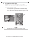
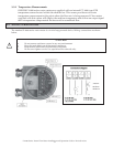
CAUTION
• Do not remove enclosure covers in any wet environment
• Keep dirt and debris out of electronics enclosure
• Keep threads lubricated (silicone based lubricant)
• Do not over tighten covers. Use special tool for removal only.