


F-2200 Series Vortex Flow Meter Installation and Operation Guide • Revised 12/08
23
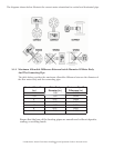
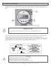
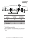
OBSTRUCTION
SEE TABLE 1
UPSTREAM
DIMENSION B 2 DIAMETERS 5 DIAMETERS
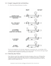
ONICON F-2000 SERIES STEAM METER, NOTE 1
300# ANSI FLANGE
ECCENTRIC REDUCER, NOTE 2
FLOW STRAIGHTENER, NOTE 3
(600# ANSI FLANGE OPTNL)
MINIMUM UPSTREAM PIPE RUN
MINIMUM DOWNSTREAM PIPE RUN
REQUIRED DIMENSIONS FOR INSTALLATIONS WITH FLOW STRAIGHTENER
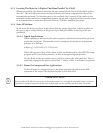
UPSTREAM
OBSTRUCTION
DIMENSION A DIMENSION B
TOTAL UPSTREAM
PIPE RUN
DISTANCE BETWEEN
FLOW METER AND
STRAIGHTENER
SINGLE 90 12 DIA 10 DIA
TEE 12 DIA 10 DIA
RDCR/EXPNDR 12 DIA 10 DIA
TWO 90’S SAME PLANE 17 DIA 15 DIA
BALL/GATE VALVE FULLY
OPEN
17 DIA 15 DIA
TWO 90’S OUT OF PLANE 22 DIA 20 DIA
CONTROL VALVE 27 DIA 25 DIA
PRV 27 DIA 25 DIA
NOTES
1. Consult ONICON for meter size and applicable meter pipe run for each application. Install
according to manufacturer’s recommendations.
2. Provide eccentric reducer and expander when required.
3. Provide fl ow straightener when required to meet recommended minimum upstream pipe run
requirements.
4. Flanges provided by contractor. Recessed fl anges are required for wafer fl ow straightener
installation.
DIMENSION A