


Parker Hannifin Corporation
Automation Actuator Division
Wadsworth, OH 44281
41
Automation
ER Series Rodless Actuator
PM-ER01/USA Maintenance Instructions and Parts List
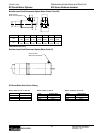
Actuator Lead (in) Holding Force N (lb)
ER50-B01 1.000 735 N (165 lb)
ER50-B02 0.500 1560 N (350 lb)
ER50-B05 0.200 3560 N (800 lb)*
ER50-A05 0.200 3560 N (800 lb)*
ER80-B01 1.000 2560 N (575 lb)
ER80-B02 0.500 5120 N (1150 lb)
ER80-B04 0.250 7120 N (1600 lb)*
ER80-A04 0.250 7120 N (1600 lb)*
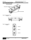
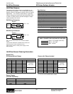
Brake Option (E, F, G, H)
A brake option is available on the ER Series size 50 and 80
rodless actuators to prevent back driving of the bearing
carriage when power is removed from the motor. The brake
is a spring loaded, friction disc type that requires a separate
power signal (24 VDC or 115 VAC) to the solenoid that
releases the brake. The brake option attaches directly to the
rear of the ball or Acme screw, preventing movement of the
bearing carriage for static conditions. Options which mount
to the rear of the actuator are not available with the brake
option.
Ordering Information
Specify brake option, voltage, and connector style within
complete actuator part number.
E: 115 VAC with flying leads and cable gland
F: 24 VDC with flying leads and cable gland
G: 115 VAC with Brad Harrison and 4 m cable
H: 24 VDC with Brad Harrison and 4 m cable
Notes:
• Brake option available on ET/ER50, ET/ER80, and ET/ER100.
• To be used as static brake only! Not intended for
dynamic braking.
• Contact factory for use with inline or reverse parallel
motor styles.
• Not available with mounting options that attach to rear of
cylinder, including B, C, E, H, and N.
• External power supply required when used with
Parker controls.
Specifications:
Mounting: Mechanically attached to end of lead screw
and enclosed in a sealed metal housing.
Voltage: 24 VDC or 115 VAC (to release)
Current: ER50: 24 VDC = 0.542A,
115 VAC = 0.113A
ER80: 24 VDC = 0.667A,
115 VAC = 0.139A
Holding Torque: ER50: 3.36 Nm (30 lb-in)
ER80: 11.2 Nm (100 lb-in)
Connector: Flying leads 3.5 m (12 ft) or
Brad Harrison 3 pin connector
(4 m mating cable supplied)
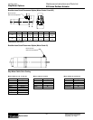
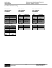
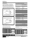
Cylinder A B C D E
ET/ER50
50.0 36.3 75.0 63.5 7
(1.96) (1.43) (2.95) (2.50) (.276)
ET/ER80
76.0 60.0 95.3 95.3 10
(3.00) (2.36) (3.75) (3.75) (.39)
ET100***
82.6 66.5 136.7 127.0 10
(3.25) (2.62) (5.38) (5.00) (.39)
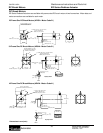
DIMENSIONS: mm
Inch equivalents for mm dimensions are shown in ( ).
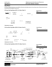
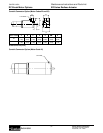
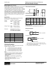
Wiring information:
Flying lead:
Connector version:
* Figure has been truncated at maximum catalog thrust rating
of standard actuator. Consult factory for higher holding forces.
** Note: 115 VAC is rectified internally.
*** C & D dimensions exceed actuator envelope.
Dimensional Information:
C
D
E
B
A
BRAKE
Chassis Ground
115 VAC** or 24 VDC
Red/Black
Red/White
115 VAC** or 24 VDC
BRAKE
Black
Black