


Parker Hannifin Corporation
Automation Actuator Division
Wadsworth, Ohio
30
Automation
PM-ER01/USA
ER Series Rodless Actuator
Maintenance Instructions and Parts List
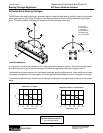
Making Adjustments
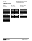
Square Rail Carriages
Square rail carriage units typically require no adjustment during the life of the actuator. Square rail bearing carriages
are installed prelubricated, and under catalogued operating conditions should not require additional lubrication. Once
the square rail bearing has exceeded its catalogued life, it may become necessary to replace the bearing set.
Excessive carriage play and increased friction torque are indications of bearing wear. Normally, the ball or lead
screw will end its useful life prior to the square rail bearing.
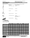
Replacement bearings are available from the Automation Actuator Division at (330) 336-3511. Please indicate the
profile size and stroke of the actuator.
Drive Belt Tensioning for Belt Drive Versions
Under normal operating conditions (as specified in Catalog 1894), the drive belt of ER Series belt driven actuators
may lose their factory set preload over time. As loss in preload may induce accuracy problems, belt slippage or
rough motion. Should this occur during use, the belt drive tension may be reset following two methods. The first
requires an inductive tension meter, available from AAD. It measures the rate of decay of the vibration of the belt
after it is struck by measuring changes in induction in the steel reinforcement strands. The second method can be
performed with simply a ruler and a weight with a known value, in which deflection of the belt is measured.
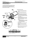
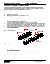
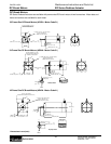
Tension Meter Method (requires Tension Meter available from AAD)
1. Remove the load attachment plate by loosening the eight screws.
2. Loosen the strip seal clamps at each end of the actuator and remove the strip seal.
3. Move the carriage to one end of the actuator; let it rest against the end of travel bumper.
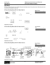
4. Measure the unsupported length of the belt from the attachment clamp at the carriage to the center of the
opposite end cap.
5. Select the mass of the belt based on the actuator size: ER32- 30 g/m, ER50- 48 g/m, ER80- 75 g/m.
6. Following the instructions provided in the meter's operating manual, measure and adjust the belt tension until the
correct preload is achieved. Belt adjustments are made by turning the screw that attaches the belt clamp to the carriage.
Clockwise rotation increases tension. Once the tension has been set, move the carriage to the other end and re-
measure the belt to verify the tension. Factory tension values are: ER32- 108 N, ER50- 212 N, ER80- 336 N.
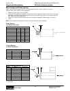
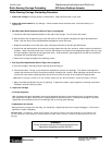
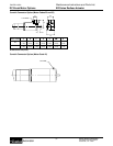
Force-Deflection Method
1. Remove the load attachment plate by loosening the eight screws.
2. Loosen the strip seal clamps at each end of the actuator and remove the strip seal.
3. Move the carriage to one end of the actuator; let it rest against the end of travel bumper.
4. Measure the unsupported length of the belt from the attachment clamp at the carriage to the center of the
opposite end cap.
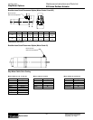
5. Insert a ruler into the actuator at the center point of the unsupported belt length. Note the height of the belt on the ruler.
6. Using the values in the table below, place the required weight at the center point of the belt and measure the deflection.
Adjust the belt tension by turning the screw that attaches the belt clamp to the carriage. Clockwise rotation increases
tension. Once the appropriate deflection has been achieved, move the carriage to the other end and re-measure the belt
to verify the tension.
Actuator Series Applied Load
lb (N)
Belt Deflection
inches (mm)
ER32 2 (9) 0.016 (0.41) x Unsupported belt length
ER50 3 (14) 0.013 (0.33) x Unsupported belt length
ER80 4 (18) 0.011 (0.28) x Unsupported belt length