Appendix D – Port & Cable Pinouts
46 DL™ User Manual Rev 3
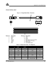
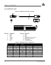
Table 15: I/O Cable – Pin Assignment
LEMO Pin
Number
Pin Description Wire Color Code
Pin 1 VARF, variable frequency Brown
Pin 2 1 PPS, one pulse per second Black
Pin 3 MSR, measure output Red
Pin 4 MKI, mark input Orange
Pin 5 STATUS , valid solutions available Yellow
Pin 6 GND Green
Pin 7 GND Blue
Pin 8 GND White
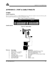
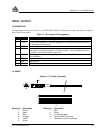
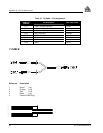
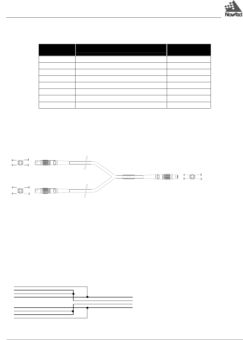
Y CABLE
Reference Description
1 Brown (-ve)
2 Orange (+ve)
3 Red (+ve)
4 Black (-ve)
5 Female LEMO Plug
5
5
5
1
2
3
4
1
2
3
4
1
2
3
4


