


8
LA000510C © 2006 Navman NZ Ltd. All rights reserved. Proprietary information and specications subject to change without notice.
DIP switch 3 interfaces with the BOOT pad of the module and allows the user to upgrade the
Flash memory. For normal operation the switch should be set to OFF. To boot from the serial
port the switch should be set to ON. This switch is enabled by the internal switch SW3.3.
3.2.4 DIP switch 4 – GPIO1/W_TICKS input
DIP switch 4 interfaces to the GPIO1/W_TICKS pad of the module. The switch is typically
OFF, but has no effect with the standard module’s software. This switch can be enabled by the
internal switch SW3.4.
3.2.5 DIP switch 5 – RTC backup power enable
DIP switch 5 provides control of the RTC backup power to the module. When set to the ON
position, the RTC backup power is applied to the module, allowing the RTC and SRAM to
continue being powered when the primary source is removed. The jumper JB5/6 must also be
in place for the backup power to be supplied. This power supply will be supplied to the module
even with the main power switch in the OFFposition.
3.2.6 DIP switch 6 – Antenna preamp power select (3.3 V or 5/12 V)
DIP switch 6 provides control of the antenna preamp voltage applied to the module. The
position of the switch determines the supply voltage (OFF = 3.3 V, ON = 5/12 V). The positions
of switches 7 and 8 also need to be considered when using the preamp function.
Note: the supplied antenna is a 3.3 V type.
3.2.7 DIP switch 7 – Antenna preamp power select (5 V or 12 V)
DIP switch 7 also controls the antenna preamp voltage applied to the module. If switch 6 is ON,
then switch 7 will determine the supply voltage to the active antenna (OFF = 12 V, ON = 5 V).
3.2.8 DIP switch 8 – Antenna preamp power enable
DIP switch 8 provides the ability to enable/disable the antenna preamp voltage to the module
depending on the antenna being used. Typically this switch is ON, enabling 3 V to be applied to
the active antenna supplied with the kit.
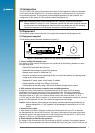
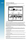
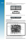
3.3 Function LEDs
There are four LEDs on the front panel of the Development Unit, indicating the status of a
selection of basic functions. The functions of the LEDs are described in the sections that follow.
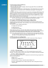
1PPS Power AUX GPIO
Figure 3-3 Function LEDs on front panel
Note that some early versions of the Development unit have different LED legends.
3.3.1 1PPS
This LED will ash ON with each transition of the 1 PPS (Pulse Per Second) output of the GPS
receiver. The 1PPS LED will begin ashing when the receiver is tracking a satellite.
3.3.2 Power
This LED indicates presence of primary DC power to the module.
3.3.3 AUX
This LED shows activity on the auxiliary serial RS232 port (DGPS).
3.3.4 GPIO
This LED indicates the state of GPIO15 , which can be set via DIP switch 2. This LED is lit
when switch 2 is set to ON. (Note that switch 2 has no effect when using standard Jupiter 20
software.)