


(1)
(2)
(3)
(4)
(5)
(6)
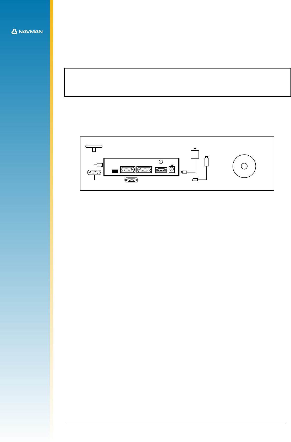
software and documentation
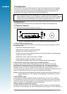
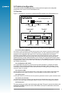
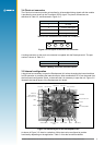
Serial Port 1
Antenna
DR
Clock
Out
Serial Port 2
-
+
DC Power
9-16Volts
4
LA000510C © 2006 Navman NZ Ltd. All rights reserved. Proprietary information and specications subject to change without notice.
1.0 Introduction
The TU10-D007-400 series of Development kits assist in the integration of either the standard
or DR version of the Jupiter 20 into a customer’s application, offering an easy to use platform
for evaluation purposes. This document provides detailed guidelines for the operation and
conguration of the Jupiter 20 GPS reciever module Development kit.
Note: before supplying power to the Development Unit, carefully review the conguration
settings outlined in section 3.0. Also, familiarise yourself with the main functional switches
and connectors on the Development Unit’s front and rear panels and with the operating
instructions described in this document for optimum receiver performance.
2.0 Equipment
This section provides a brief overview of the equipment included in the Development kit.
2.1 Equipment supplied
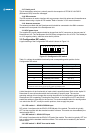
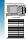
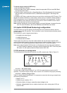
This kit should contain the items illustrated in Figure 2-1.
Figure 2-1 Equipment supplied in the Jupiter 20 GPS Development kit
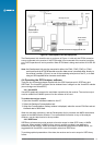
1. Jupiter 20 GPS Development Unit
The Jupiter 20 GPS receiver Development Unit includes all of the following hardware to allow
thorough evaluation:
• Dual RS232 level serial data I/O ports
• Selectable bias voltages for active GPS antennas
• Backup power source for SRAM and RTC
• Provision to insert a current measuring device to monitor both primary and backup power
usage under various conditions
• Regulated DC power supply to the Jupiter 20 module
• Status indication through four LEDs on front panel
• Congurable functionality using a DIP switch accessed through the front panel
2. GPS antenna with pre-amp, magnetic base and SMA connector
A magnetic-mount active antenna is supplied along with an RF cable (RG-316) already
terminated with the proper connector for the Development Unit. The nominal measured
attenuation of the cable with connectors is approximately 5 dB. The supplied active antenna
should be biased at +3 VDC, but a different active antenna with a bias of either +3, +5 or
+12 VDC may be used. Refer to section 3.2 to ensure that the conguration switches on the front
panel of the Development Unit are set to select the appropriate bias voltage.
Caution: ensure antenna power switches are properly set before connecting the antenna. An
antenna designed for +3 VDC operation will be damaged if connected to a +12 VDC
source.
3. Serial interface cable
A serial cable is provided to interface between the Development Unit and a PC, or between
the Development Unit and a DGPS receiver. This cable is terminated at both ends with female
connectors to match the male connectors on the Development Unit and the PC. If the PC only
supports a USB port, an RS232/USB converter could be used.
4. Power adapter for 240/120 VAC operation
DC power for the Development Unit is provided by an AC/DC converter or automobile adapter.
The AC/DC converter operates from nominal 120/240 VAC input and gives 12 VDC at 500 mA out.