


6
LA000510C © 2006 Navman NZ Ltd. All rights reserved. Proprietary information and specications subject to change without notice.
3.0 Technical conguration
This section provides a detailed description of all the technical aspects and congurable
functionality of the Jupiter 20 GPS Development Unit.
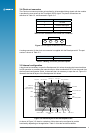
3.1 Overview
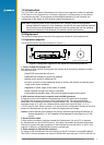
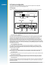
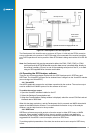
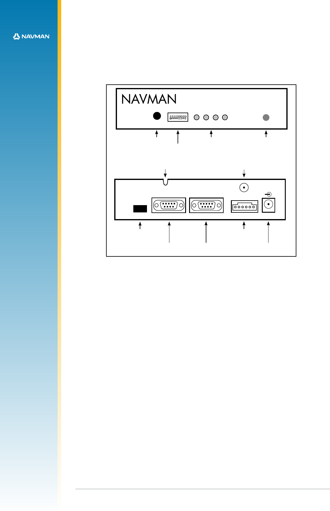
Figure 3-1 illustrates the connectors, switches and LEDs available on the Development Unit.
1 2 3 4 5 6 7 8
CTS 2 06-8 T11 4
'03$EVELOPMENT5NIT
#/.&)'52!4)/.
0/7%2
2%3%4
4)-%
-!2+
0/7%2 $'03
!#4)6%
.-%!
!3352%$
power switch
conguration switch
function LEDs
reset switch
Serial Port 1
Antenna
DR
Clock
Out
Serial Port 2
-
+
DC Power
9-16Volts
1PPS output
comm 1
NMEA & binary
comm 2
(RTCM)
dead reckoning
input signals
DC input J1
‘U’ slot for antenna
cable (custom)
SMA antenna
connector
Figure 3-1 Front and back panels of the Jupiter 20 development unit
3.1.1 Power switch (ON/OFF)
The switch on the front panel controls primary power to the Jupiter 20 receiver module inside.
The power status LED (see section 3.3) indicates status: if lit, the module has primary power
supplied. If the conguration DIP switch 5 is on and Jumper JB5/6 linked, the module’s
secondary supply SRAM and RTC will continue to be powered when the power switch is off.
Only removal of the DC power input at the rear of the unit will stop secondary power being
applied (assuming Jumper JB5/6 and switch 5 are correctly set). Having this secondary power
supply applied means that the Jupiter 20 will have a ‘hot start’ capability when primary power is
re-applied within 4 hours, and a ‘warm start’ thereafter, by maintaining last position, current time
and satellite ephemerides.
3.1.2 Conguration DIP switch
The conguration DIP switch on the front panel provides the ability to congure the Jupiter
20 module, offering exibility depending on the specic application. Refer to section 3.2 for
a description of the functionality of each individual switch, including the typical settings when
using the Jupiter 20 module.
3.1.3 Function LEDs
The four LEDs on the front panel indicate the current status of basic features associated with
the Development Unit. Refer to section 3.3 for a description of the function of each LED.
3.1.4 Reset switch
A reset push button is provided on the front panel to generate a receiver system hardware reset.
3.1.5 Clock out connector
The Clock out connector, located on the rear panel of the Development Unit, can be used to
provide module generated timing signals. Refer to section 3.4 for more detailed information.
3.1.6 Serial port 1
This host serial port is used to send and receive serial data. This port is used as the default, with
transmission in NMEA format at the rate of 9600 Baud. Use 9-pin D-subminiature connectors
with these serial ports.