


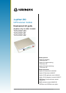

LA000510C © 2006 Navman NZ Ltd. All rights reserved. Proprietary information and specications subject to change without notice.
Contents
1.0 Introduction .......................................................................................................4
2.0 Equipment..........................................................................................................4
2.1 Equipment supplied ...................................................................................................... 4
2.2 Equipment required ...................................................................................................... 5
3.0 Technical conguration ....................................................................................6
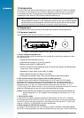
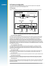
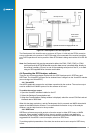
3.1 Overview ....................................................................................................................... 6
3.1.1 Power switch (ON/OFF) ........................................................................................ 6
3.1.2 Conguration DIP switch ...................................................................................... 6
3.1.3 Function LEDs ...................................................................................................... 6
3.1.4 Reset switch ......................................................................................................... 6
3.1.5 Clock out connector .............................................................................................. 6
3.1.6 Serial port 1 .......................................................................................................... 6
3.1.7 Serial port 2 .......................................................................................................... 7
3.1.8 DR connector ........................................................................................................ 7
3.1.9 Antenna connector ............................................................................................... 7
3.1.10 DC power input ................................................................................................... 7
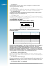
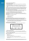
3.2 Conguration DIP switch .............................................................................................. 7
3.2.1 DIP switch 1 – GPIO3 /GYROIN input ................................................................. 7
3.2.2 DIP switch 2 – GPIO15 /FR input ......................................................................... 7
3.2.3 DIP switch 3 – BOOT from serial mode ............................................................... 7
3.2.4 DIP switch 4 – GPIO1/W_TICKS input ................................................................. 8
3.2.5 DIP switch 5 – RTC backup power enable ........................................................... 8
3.2.6 DIP switch 6 – Antenna preamp power select (3.3 V or 5/12 V) .......................... 8
3.2.7 DIP switch 7 – Antenna preamp power select (5 V or 12 V) ................................ 8
3.2.8 DIP switch 8 – Antenna preamp power enable .................................................... 8
3.3 Function LEDs .............................................................................................................. 8
3.3.1 1PPS ..................................................................................................................... 8
3.3.2 Power ................................................................................................................... 8
3.3.3 AUX ...................................................................................................................... 8
3.3.4 GPIO .................................................................................................................... 8
3.4 Clock out connector ..................................................................................................... 9
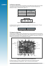
3.5 Internal conguration .................................................................................................... 9
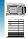
3.6 Jupiter 20 module on adapter board ...........................................................................11
4.0 Operating instructions ................................................................................... 12
4.1 Initial connection and operation ..................................................................................12
4.1.1 Install the supplied SiRFdemo on your PC: .........................................................12
4.1.2 Set up the hardware: ...........................................................................................12
4.2 Positioning the GPS antenna ......................................................................................12
4.3 Connecting an RTCM differential source ....................................................................12
4.4 Operating the GPS Analyser software ........................................................................13
4.4.1 VisualGPS ...........................................................................................................13
4.4.2 SiRFDemo ...........................................................................................................13
5.0 Jupiter 20 DR (Dead Reckoning) conguration ........................................... 14
5.1 DR connector pin conguration ...................................................................................14
5.1.1 Pin 1 – DC power supply......................................................................................14
5.1.2 Pin 2 – Heading rate gyro input ...........................................................................14
5.1.3 Pin 3 – Direction F/R sensor ................................................................................15
5.1.4 Pin 4 – Reserved .................................................................................................15
5.1.5 Pin 5 – Speed pulses ...........................................................................................15
5.1.6 Pin 6 – Ground .....................................................................................................15
6.0 Acronyms used in this document ................................................................. 15