


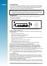
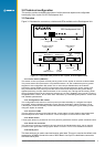
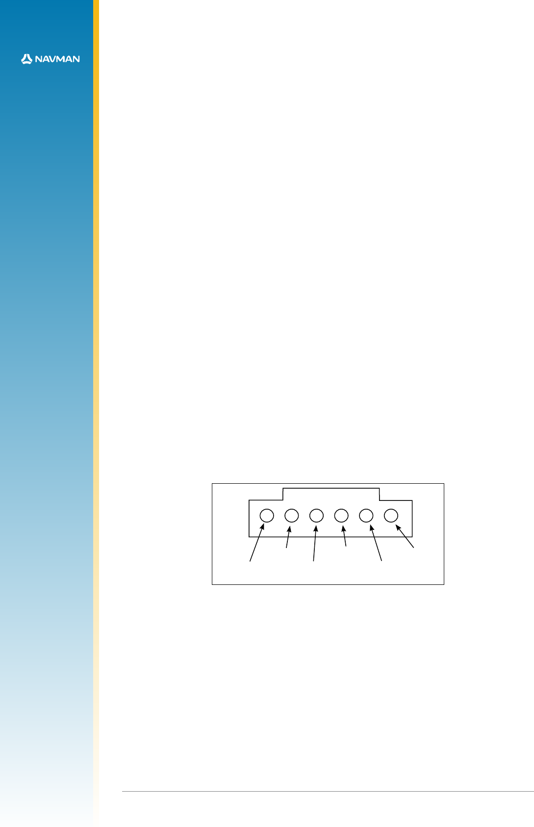
J5
+3.3 VDC,
or +5 VDC
direction
F/R
reserved
wheel
ticks
1
2
3
4 5 6
gyro ground
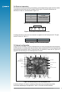
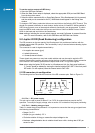
Figure 5-1 DR interface connector (rear of unit)
5.1.1 Pin 1 – DC power supply
This pin can be used to power at either 3.3 or 5 VDC for external devices used in the DR
operation. To modify the supply voltage, refer to section 3.5 for details of the jumper positioning.
5.1.2 Pin 2 – Heading rate gyro input
Table 5-1 details the gyro requirements. It is important to ensure that the rate gyro signals have
the following characteristics:
• Range: 0 to 5 V
• Output (no gyro rotation): 2.5 V
• Clockwise rotation of the gyro causes the output voltage to rise
• Maximum voltage deviation due to rotation should occur with a turning rate of 90º per
second or less
14
LA000510C © 2006 Navman NZ Ltd. All rights reserved. Proprietary information and specications subject to change without notice.
To set the receiver output to SiRF binary
1. Open the SiRFDemo software.
2. When the Data Source setup is displayed, select the appropriate COM port and 9600 Baud
from the drop down menu.
3. Select the Action menu and click on Open Data Source. If the Development Unit is powered,
and the serial port is connected to the PC, NMEA data should appear in the Debug View
window.
To change to SiRF binary, select the Action menu and click on the Switch to SiRF Protocol. This
should now present information in each window, similar to that of VisualGPS. Whilst enabled in
SiRF binary protocol, more of the analysis software’s functionality can be accessed. To switch
back into NMEA mode, select the Action menu and click on Switch to NMEA Protocol. Select
9600 for the baud rate and click on the Send button.
Note: settings, including the current output protocol, are reset if all power is removed from the
unit. For more information, refer to the SiRFDemo and SiRFFlash User Guides.
5.0 Jupiter 20 DR (Dead Reckoning) conguration
The DR connector on the rear panel of the Development Unit provides an interface with the
external inputs under DR operation. This functionality is only to be used when evaluating Jupiter
20 DR modules.
The connector is used for signals transmitted by:
• An angular rate sensor (gyro)
• A wheel ticks source
• A forward/reverse indicator
These signals are present on many late model vehicles and may be used to assist the DR
receiver in determining position accuracy during the loss of signal conditions. Direct connection
to the vehicle is not normally possible as the inputs need to be 3 V logic level signals.
Note: when using the Jupiter 20 DR version in a Development Unit, the front panel switches 1,
2, 3 and 4 should be isolated by turning the internal switches SW3 OFF. If the front panel
DIP switch 3 is still required, leave the internal switch SW3.3 ON.
5.1 DR connector pin conguration
The following sections describe the functions of the DR connector pins. Refer to Figure 5-1.