


7
LA000510C © 2006 Navman NZ Ltd. All rights reserved. Proprietary information and specications subject to change without notice.
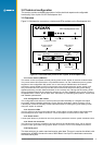
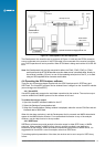
3.1.7 Serial port 2
This is the auxiliary serial port, primarily used for the reception of RTCM SC-104 DGPS
(Differential GPS) correction messages.
3.1.8 DR connector
The DR connector is used to interface with a gyroscope, wheel tick pulses and forward/reverse
indicator when using a Jupiter 20 DR module. Refer to section 3.5 for more information.
3.1.9 Antenna connector
The antenna provided with this Development kit should be connected to the SMA connector
located on the rear panel of the Development Unit.
3.1.10 DC power input
The supplied DC power adapter should be plugged into the DC connector on the rear panel of
Development Unit. The Development Unit will accept voltages from 9 to 16 VDC. The middle pin
on J1 is negative polarity, while the outer shell is positive.
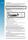
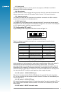
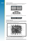
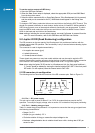
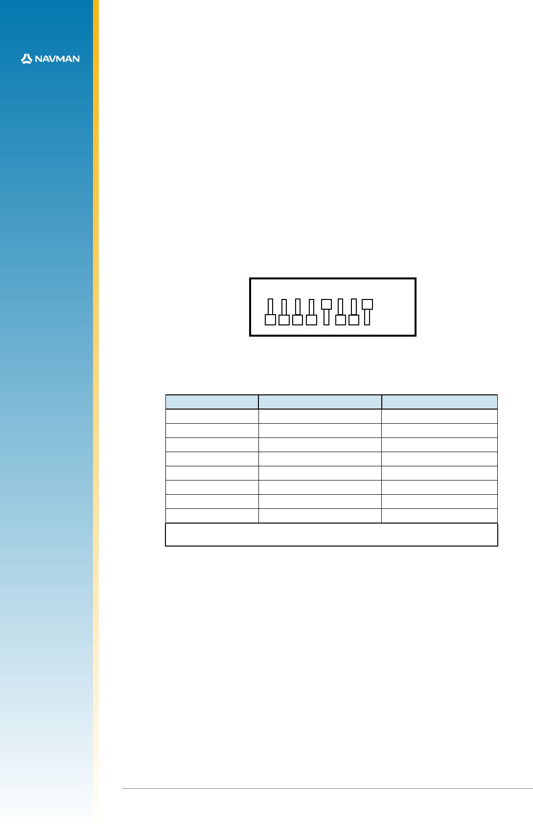
3.2 Conguration DIP switch
A typical setting of the Conguration DIP switch is shown in Figure 3-2.
ON
OFF
1 2 3 4 5 6 7 8
Figure 3-2 Conguration DIP switch
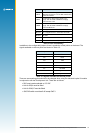
Table 3-1 outlines the available functionality and corresponding switch position for the
Conguration DIP switch.
Switch Description Typical setting
1 GPIO3/GYROIN* OFF (high)
2 GPIO15/FR* OFF (high)
3 Serial BOOT OFF (normal run)
4 GPIO1/W_TICKS* OFF (high)
5 RTC BACKUP POWER ON (enabled)
6 PREAMP power select OFF (3 V)
7 PREAMP power select OFF (12 V)
8 PREAMP power enable ON (enabled)
* These functions have been disabled by internal switch SW3 to allow correct operation of
the antenna current sense circuits on the Jupiter 20 adapter board.
Table 3-1 DIP switch settings
A brief description of the functionality of each switch is specied below. Refer to the Jupiter 20
Data sheet for more information about the functionality of specic pads. The receiver
operating settings will not change after moving the position of a conguration switch while the
Development Unit is operating. Pressing the reset switch, or turning the unit OFF and ON will
enable the settings to take effect in the receiver. The recommended method for reconguration
is to switch the unit OFF, modify the switch positions, then re-apply the power.
3.2.1 DIP switch 1 – GPIO3 /GYROIN input
DIP switch 1 interfaces with the GPIO3 /GYROIN pad of the module. The switch is typically
OFF, but has no effect with the standard module’s software. This switch can be enabled by the
internal switch SW3.1.
3.2.2 DIP switch 2 – GPIO15 /FR input
DIP switch 2 interfaces with the GPIO15 /FR pad of the module. The switch is typically OFF, but
has no effect with the standard module’s software. This switch can be enabled by the internal
switch SW3.2.
3.2.3 DIP switch 3 – BOOT from serial mode