


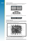
Jupiter 20 module
antenna
power LED GPS x LED
J1
J2
(not normally tted)
RTC backup battery
(not normally tted)
11
LA000510C © 2006 Navman NZ Ltd. All rights reserved. Proprietary information and specications subject to change without notice.
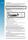
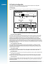
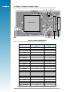
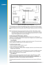
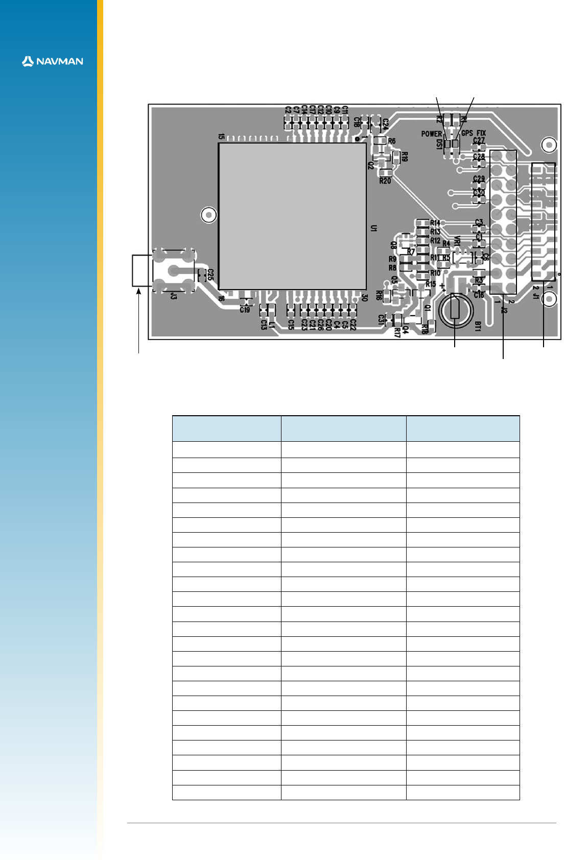
3.6 Jupiter 20 module on adapter board
Figure 3-6 shows the adapter board with the positions of the connectors and indicators.
Figure 3-6 Jupiter 20 adapter board
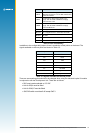
Table 3-6 lists the pin congurations for the J1 and J2 connectors.
Jupiter function J2 (2.54 mm pitch header)
pin no.
J1 (2 mm pitch header)
pin no.
V_ANT 1 1
VCC_RF 2
V_BATT 3 3
VDD 4 4
M_RST 5 5
GPIO3/GYRO IN 6 6
GPIO15/FR 7 7
BOOT 8 8
GPIO1/W TICKS 9 9
RFON 10
GND 10
TXA 11 11
RXA 12 12
GPIO5/SDI 13
GND 13
TXB 14 14
RXB 15 15
GPIO7/SCK 16
GND 17 16
GPIO6/SDO 18
GND 17
GND 18
1PPS 19 19
GPS_FIX/GPIO10 20
Table 3-6 Connections J1 (2 mm pitch header) and J2 (2.54 mm pitch header)