15
LA000510C © 2006 Navman NZ Ltd. All rights reserved. Proprietary information and specications subject to change without notice.
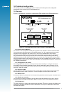
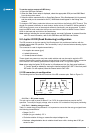
The gyro should be mounted so that its sensitive axis is as near vertical as practical. Deviations
from the vertical will reduce sensitivity for heading changes in the horizontal direction.
Experiments have shown that acceptable performance can be achieved with mounting
deviations of several degrees, but a better performance is achieved when the gyro is mounted
closer to vertical.
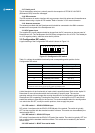
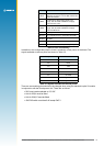
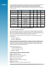
Characteristics Symbol Condition Minimum Standard Maximum Unit
Supply voltage Vcc +4.5 +5.0 +5.5 VDC
Max. angular velocity ω max –80 +80 deg/s
Output Vo angular velocity = 0 at –30
~ 80°C
2.200 2.500 2.800 VDC
Scale factor Sv at –30 ~ 80°C 19.3 22.2 25.1 mV/deg/s
Asymmetry CW & CCW 3 deg/s
Temp coefcient scale
factor
reference temp:
–30 ~ 80°C
±10 %FS
Temp coefcient drift reference temp:
–30 ~ 80°C
9 deg/s
Noise level 7kHz noise 20 mVrms
Linearity in the maximum angular
velocity range
0.5 %FS
Operating temp range Topr –40 85 °C
Table 5-1 Gyro input specications
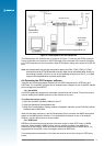
5.1.3 Pin 3 – Direction F/R sensor
Input from a signal that is normally at +0 V, but rises to +3 V when the vehicle is in the reverse
gear. Use of this signal is optional; if it is not used, the effect of occasional reversing by the
vehicle will not signicantly degrade navigation performance. To ensure minimum current under
backup power, be sure that this input is not pulled up external to the board.
If this signal is not connected, switch SW3.2 should be left on, with DIP switch 2 also on to
select ‘forward’.
5.1.4 Pin 4 – Reserved
5.1.5 Pin 5 – Speed pulses
The input to this pin is a pulse train generated in the vehicle. If this signal is derived from the
vehicle’s electrical system, external level shifting for this signal is required. The pulse frequency
is proportional to the vehicle velocity. These pulses, or wheel ticks, are generated in most
vehicles by the ABS (Anti-lock Braking System), the transmission, or the drive shaft. System
design must restrict the pulses between 0 and 3 V.
Detection limits are as follows:
• Minimum detectable rate: 1 Hz
• Maximum detectable rate: 4 kHz
5.1.6 Pin 6 – Ground
6.0 Acronyms used in this document
1PPS: One Pulse Per Second
DGPS: Differential Global Positioning System
GPIO: General Purpose Input Output
GPS: Global Positioning System
NMEA: National Marine Electronics Association
RTC: Real Time Clock
RTCM: Radio Technical Commission for Maritime services