


10
LA000510C © 2006 Navman NZ Ltd. All rights reserved. Proprietary information and specications subject to change without notice.
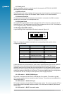
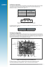
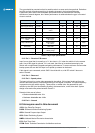
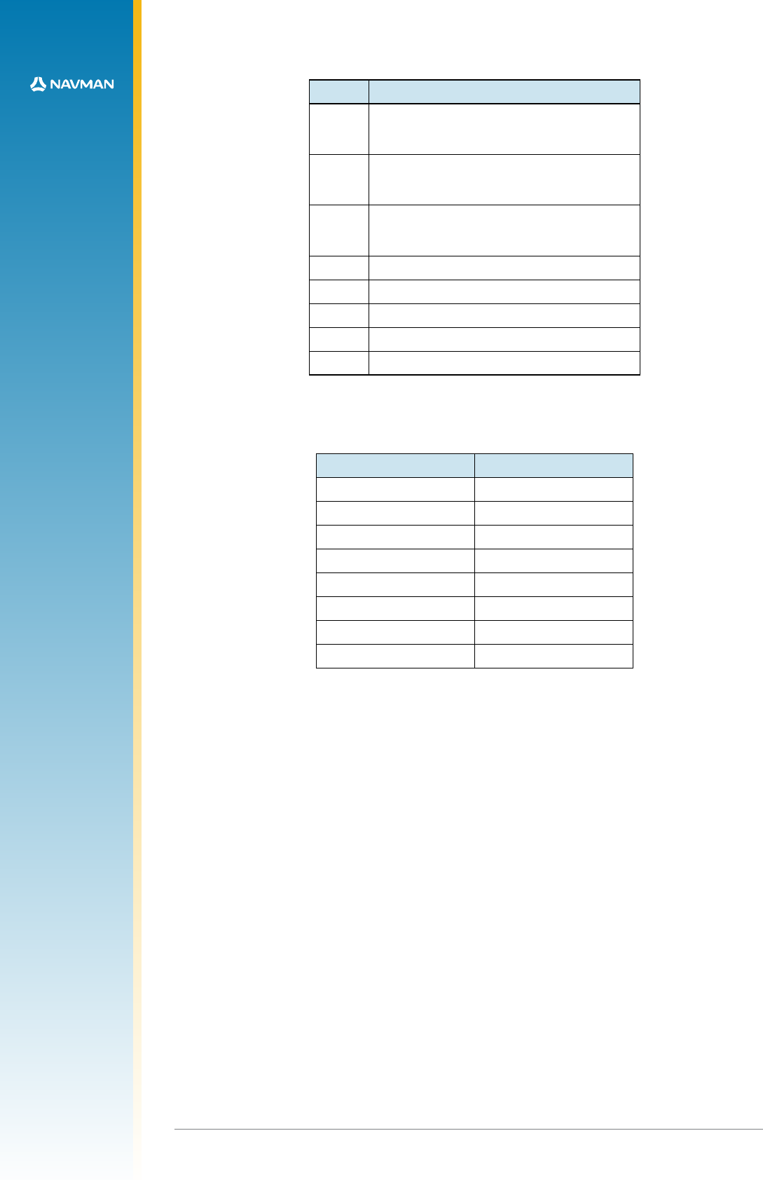
Pins Function when linked
JB1/2
Current link for 5 V supply. Can be used to
determine current on 5 V rail. Not used for the
Jupiter 20 module.
JB3/4
Current link for the primary power 3.3 V
supply. Can be used to determine supply
current for 3.3 V rail.
JB5/6
Current link for the secondary power RTC
supply. Can be used to determine supply
current for RTC rail.
JB10/11 5 V supplied to Pin 1 of the DR connector
JB11/12 3.3 V supplied to Pin 1 of the DR connector
JB13/14 not used
JB14/15 not used
JB16/17 Internal interface enable (normally tted)
Table 3-4 Pin functionality
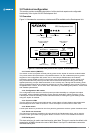
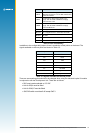
In addition to the congurable jumpers, there is a selection of test points on the board. The
signals available on the test points are shown in Table 3-5.
Test point Function
E1 TXA
E2 RXA
E3 TXB
E4 RXB
E6 1PPS
E7 not used
E8 ground
E9 ground
Table 3-5 Signals available on the test points
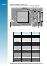
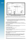
There are some settings that should not be changed when using the standard Jupiter 20 module
in conjunction with the Development Unit. These are as follows:
• SW2 must remain selected on 3.3 VDC
• Link for JB3/4 must be tted
• Link for JB16/17 must be tted
• SW3 DIP switch must be all off except SW3.3