


G-PILOT 3100 Installation Manual
NAVMAN
29
Electrical
Heavy duty power supply 10.5 to 16.5 V
DC, 20 A maximum
Light duty power supply 10.5 to 16.5 V DC:
Main unit: 80 mA.
Each display unit, 30 mA without
backlighting, 110 mA with full
backlighting.
Other optional instruments: refer to the
instrument’s operation manual.
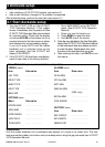
Interfaces
NavBus connection to other Navman
instruments.
NMEA 0183 outputs: HDG, HDT, RSA;
inputs APA, APB, BOD, BWC, MWD,
MWV, RMA, RMB, RMC, VHW, VTG,
XTE
NMEA 0183 ports:
NMEA 1: Input
NMEA 2: Can be programmed to be an
input or output
Standards compliance
EMC compliance
USA (FCC): Part 15 Class B.
Europe (CE): EN50081-1, EN50082-1
New Zealand and Australia (C Tick):
AS-NZS 3548.
Environment:
Compass, gyro, rudder feedback unit:
completely waterproof.
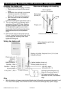
Display unit: IP66 from front when
correctly mounted.
Main unit: requires a cool, dry, clean
environment.
Appendix A - Specifi cations
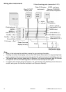
Main unit terminal block connections:
Terminal Signal
1 Heavy duty power positive, 10.5 to
16.5 V DC, 20 A maximum
2 Heavy duty power negative
3 Steering drive negative output
4 Steering drive positive output
Main unit connector connections:
Terminal Signal
1 Light duty power positive, 10.5 to
16.5 V DC, 80 mA maximum
2 Light duty power supply common
3 NavBus +
4 NavBus -
5 NMEA common
6 NMEA in 1
7 NMEA in 2
8 Steering clutch relay drive output,
switched ground to turn relay on,
30 V DC, 300 mA maximum
Display unit power/data cable wires:
Wire Signal
Red Power positive, 10.5 to 16.5 V DC,
30 mA without backlighting, 110
mA with full backlighting
Black Power negative
Orange NavBus +
Blue NavBus -
Yellow Factory use (isolate, do not cut)
White Factory use (isolate, do not cut)
Green External alarm, switched to
ground,
30 V DC and 250 mA max.
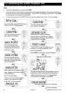
Appendix B - Alarm and warning messages
Alarm display Reason for message Recommended action by user Notes
BAT ALARM Battery voltage is less than the Check batteries a
minimum value set by the user Disengage G-PILOT if voltage too low
CAL ERROR
The G-PILOT rudder feedback unit
Calibrate both the units a
or compass unit is not calibrated (see sections 5-2 and 6-1)
CCH ERROR The clutch current is to high Check clutch connection a s
CE ALARM Course error has exceeded the Manually steer boat towards course a
maximum value set by the user
CSU ERROR Compass not sending data to Check compass is connected to a s
main unit main unit; Service compass
CUR ALARM The motor current exceeded the Check steering drive is not jammed a s
maximum value set by the user Increase the alarm value