G-PILOT 3100 Installation Manual
NAVMAN
24
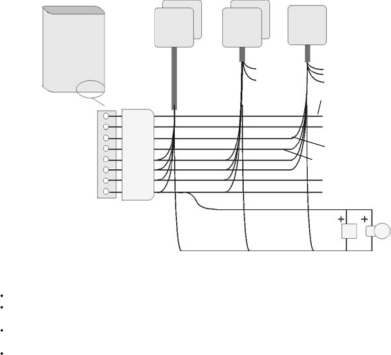
Wiring other instruments
Main unit
Display
units
More G-PILOT
display units
Follow the wiring guide (see section 3-2-2).
Other 3100 series
instruments
3100
units
A GPS, such as a
Navman TRACKER
5000 series chartplotter
NMEA in/out
NMEA
in & out
GPS NMEA out
GPS NMEA common
Power,
NMEA in
GreenGreen
Beepers and lights
(see previous page)
Green (from one
display unit only)
Connector cover
Note:
Refer to the instrument’s installation manual for more wiring information.
If adding more than three display units or other 3100 series instruments, fi t a separate light-duty
power supply for the extra instruments (see section 3-4 or the instrument’s installation manual)
The external alarm outputs (green wire) of Navman 3100 series instruments and 5000 series
chartplotters can be connected together to drive the external beepers and lights.
In systems with several other instruments, we recommend using NavBus junction boxes to
simplify wiring (see the NavBus Installation and Operation Manual).
Clutch relay out, 8
NMEA 2, 7
NMEA in 1, 6
NMEA common, 5
NavBus -, Blue 4
NavBus +, Orange 3
Ground, Black 2
12 V power +, Red 1
Light duty power
(see section 3-4-1)
Clutch, optional
(see section 3-4-2)
GPS


