


ENGINE <4D6> -
Cylinder Head Gasket
11C-25
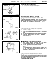
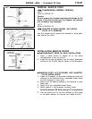
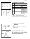
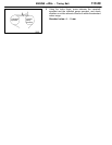
4. Tighten the bolts by the following procedure.
Step Operation Remarks
1 Tighten to 88 Nm. Carry out in the order
shown in the illustration.
2 Fully loosen. Carry out in the reverse
order of that shown in the
illustration.
3 Tighten to 39 Nm. Carry out in the order
shown in the illustration.
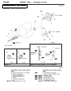
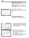
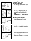
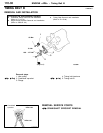
4 Tighten 90
_
of a turn. In the order shown in the
illustration. Mark the head
of the cylinder head bolt
and cylinder head by paint.
5 Tighten 90
_
of a turn. In the order shown in the
illustration. Check that the
painted mark of the head
bolt is lined up with that of
the cylinder head.
Caution
(1) Always make a tightening angle just 90
_
. If it is less
than 90
_
, the head bolt will be loosened.
(2) If it is more than 90
_
, remove the head bolt and repeat
the procedure from step 1.
"
C
A
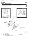
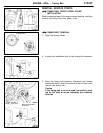
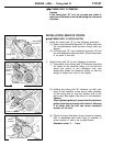
ROCKER ARM AND SHAFT ASSEMBLY
INSTALLATION
1. Install the rocker arm and shaft assembly to the bearing
caps.
2. Set the rocker arm springs into the bearing cap indents.
3. Check the valve clearance and adjust if necessary.
(Refer to P.11C-8.)
"
D
A
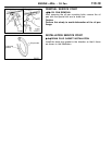
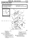
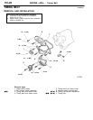
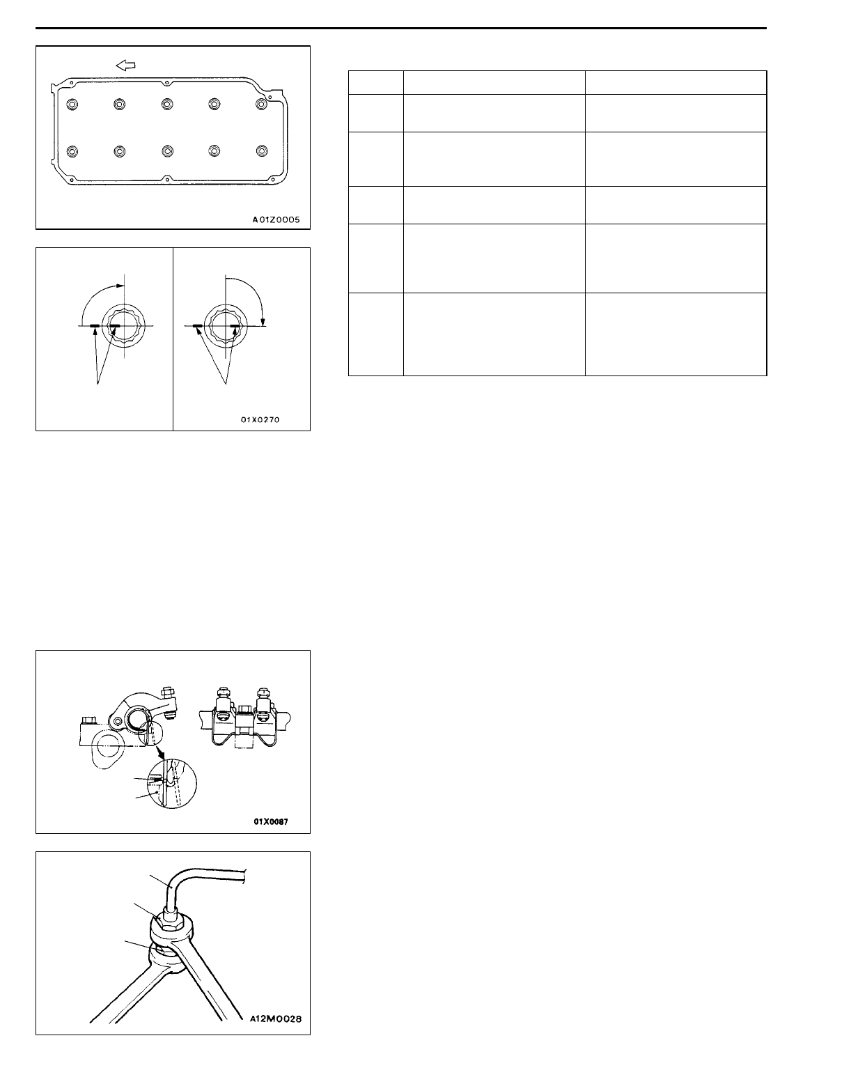
FUEL INJECTION PIPE INSTALLATION
When tightening the nuts at both ends of the fuel injection
pipe, hold the delivery holder (for pump side) and the fuel
injection nozzle assembly (for nozzle side) with a wrench,
and tighten the nuts to the specified torque.
Intake side
Front of engine
Exhaust side
86139
104257
Step 4
90
_
Painted mark
Step 5
90
_
Painted mark
Indent
Bearing cap
Fuel injection pipe
Nut
Nozzle holder