111
APPENDICES
A
Appendix 4 Special Register (SD) for MELSECNET/H (MELSECNET/10 Mode) Remote I/O Station
SD5
Error common
information
Error common
information
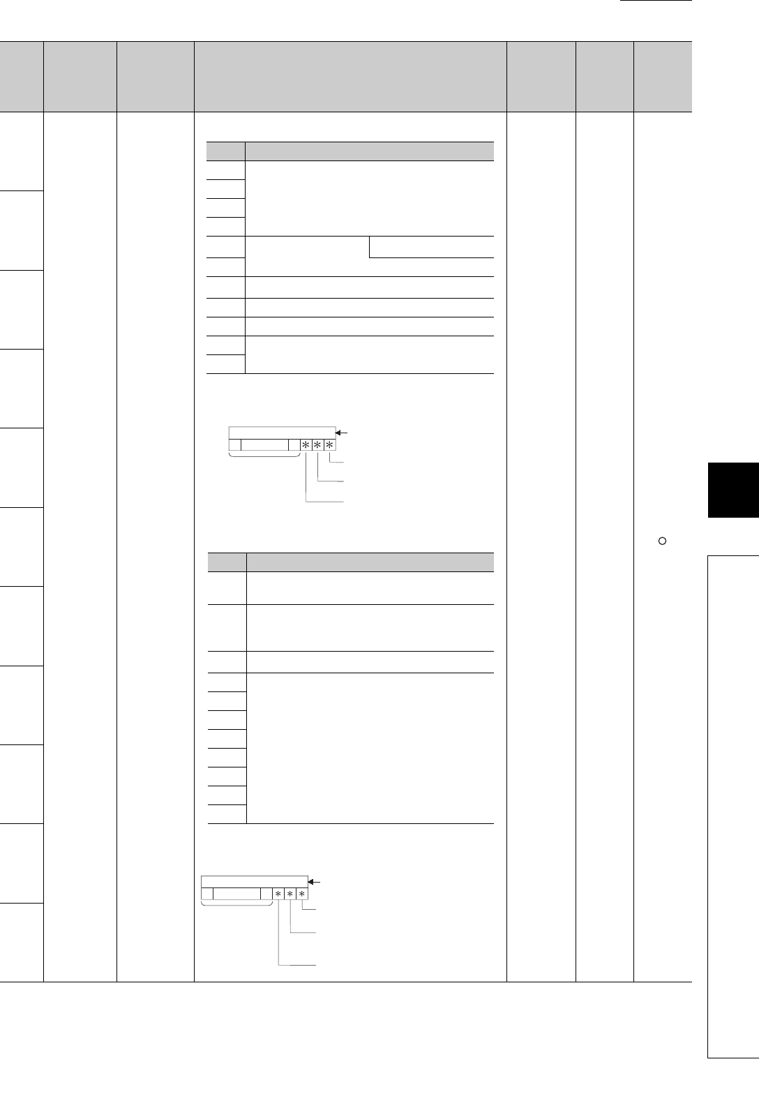
4) Program error location
*1 For extension names, refer to *6.
*2 The description of the bit pattern is as follows:
5) Reason(s) for system switching
*3 Stored value of the tracking flag
Whether the tracking data is enabled or disabled can be set.
S
(Error)
New
Rem
SD6
SD7
SD8
SD9
SD10
SD11
SD12
SD13
SD14
SD15
No. Name Meaning Explanation
Set by
(When Set)
Corres-
ponding
ACPU
D9
Corres-
ponding
CPU
No. Description
SD5
File name
(ASCII code: 8 characters)
SD6
SD7
SD8
SD9
Extension
*1
2E
H
(.)
SD10 (ASCII code: 3 characters)
SD11
Pattern
*2
SD12 Block No.
SD13 Step No./transition No.
SD14
Sequence step No. (L)
Sequence step No. (H)
SD15
SFC block specified (1)/
not specified (0)
0000
to
0123415 14 to
SFC step specified (1)
/not specified (0)
SFC transition specified (1)/
not specified (0)
(Not used)
(Bit number)
No. Description
SD5
System switching cause (0: Auto system switching/
1: Manual system switching)
SD6
System switching direction
(0: Stanby system control system/
1: Control system stanby system)
SD7
Tracking flag
*3
SD8
(Empty)
SD9
SD10
SD11
SD12
SD13
SD14
SD15
0000 to
012341514 to
(Not used)
(Bit number)
Invalid work data
invalid (0)/valid (1)
System data
(SFC active step information)
invalid (0)/valid (1)
System switching cause invalid (0)/valid (1)


