


19
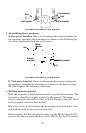
If the transducer's face isn't parallel with the ground, remove the
transducer and ratchets from the bracket. Place the ratchets into the
holes in the bracket with the letter "B" aligned with the dot stamped
in the bracket.
Reassemble the transducer and bracket and place them against the
transom. Again, check to see if you can move the transducer so it's
parallel with the ground. If you can, then go to step 3A. If it doesn't,
repeat step 2A, but use a different alignment letter until you can
place the transducer on the transom correctly.
Insert bolt and check transducer position on transom.
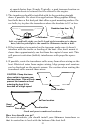
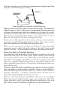
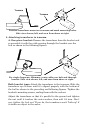
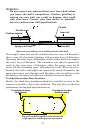
B. Two-piece bracket: Assemble the transducer and bracket as shown
in the following figure. Temporarily slide the bolt though the transducer
assembly but don't tighten the nut at this time. Hold the assembled
transducer and bracket against the transom. Looking at the transducer
from the side, check to see if it will adjust so that its face is parallel to
the ground. If it does, then the "A" positions are correct for your hull.
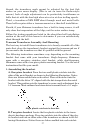
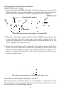
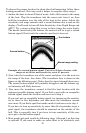
If the transducer's face isn't parallel with the ground, remove and
disassemble the transducer and ratchets. Place the ratchets into the
bracket holes with the letter "B" aligned with the bracket alignment
mark. Place them on the transducer aligned with the 12 o'clock posi-
tion on the transducer stem.
Reassemble the transducer and bracket and place them against the
transom. Again, check to see if you can move the transducer so it's
parallel with the ground. If you can, then go to step 3B. If it doesn't,
repeat step 2B, but use a different alignment letter until you can
place the transducer on the transom correctly.
Ratchets