


6 OPERATIONAL EXAMPLES OF APRS
44 CONTENTS TH-D72A/E
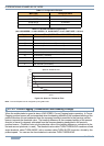
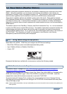
Table 6-2 Configuration Example
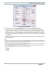
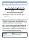
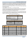
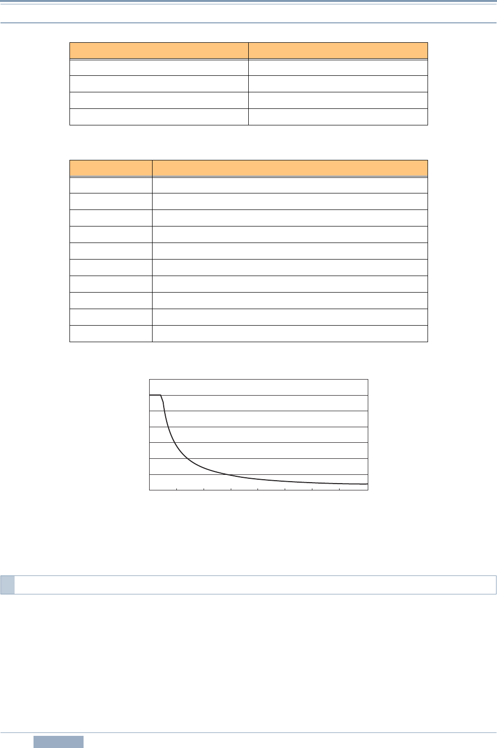
Table 6-3 Variable Rate Beaconing Example:
(with LOW SPEED = 5, HIGH SPEED = 70, SLOW RATE = 30 min, FAST RATE = 120 sec)
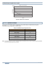
Figure 6-4 Speed vs TX Interval Time
Note: The unit of Speed can be configured by using Menu 3V0.
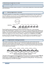
When the mobile station’s speed is above LOW SPEED, Corner Pegging begins operating. A Corner
Pegging position beacon will be transmitted when the heading difference (the compass heading of the
present direction of travel subtracted from the compass heading transmitted in the previous position
beacon) exceeds the threshold value. The heading difference is the compass heading of the present
direction of travel (in degrees) subtracted from the compass heading transmitted in the previous
position beacon. (Technical note: only the absolute value of the heading difference, normalized to the
first and second quadrants, is used.) The threshold value called TURN THRESHOLD combines a fixed
angle threshold, called TURN ANGLE, with a constant called TURN SLOPE, times ten, divided by the
present speed. You can use the formula below to calculate TURN THRESHOLD.
Menu Item Configured Value
LOW SPEED 5
HIGH SPEED 70
SLOW RATE 30 minutes
FAST RATE 120 seconds
Speed TX interval Time (FAST RATE = HIGH SPEED ÷ Speed)
80 120 seconds (2 minutes)
70 120 seconds (2 minutes)
60 140 seconds (2 minutes and 20 seconds)
50 168 seconds (2 minutes and 48 seconds)
40 210 seconds (3 minutes and 30 seconds)
30 280 seconds (4 minutes and 40 seconds)
20 420 seconds (7 minutes)
10 840 seconds (14 minutes)
5 1680 seconds (28 minutes)
0 1800 seconds (30 minutes)
6.1.5.2 Corner Pegging (Transmission after Heading Change)
25
20
35
30
15
10
5
0
10 20 30 40 50 60 70 8
0
Speed
Speed vs TX Interval Time
TX Interval Time
(min.)