3535
T
R
A
N
S
A
X
L
E
/
M
O
T
O
R
/
B
R
A
K
E
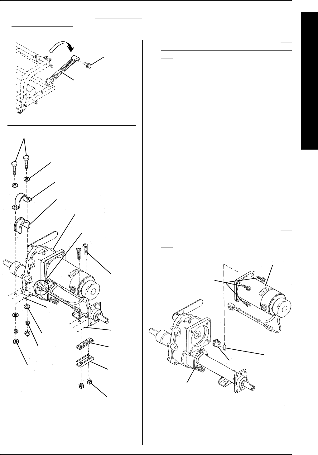
FIGURE 3 - REPLACING MOTOR/BRAKE
ASSEMBLY
Nylock Bolts
Motor/Brake
Assembly
Transaxle
Plate
Bushing
REPLACING MOTOR/BRAKE
ASSEMBLY (FIGURE 3)
1 Remove the transaxle assembly. Refer to RE-
MOVING/INSTALLING TRANSAXLE ASSEM-
BLY in PROCEDURE 6 of this manual.
2. Remove the four EXISTING (4) nylock socket
bolts that secure the motor/brake assembly to
the transaxle assembly.
3. Remove the EXISTING motor/brake assembly
from the transaxle assembly.
4. Remove the EXISTING plate and bushing from
the transaxle assembly.
5. Position the NEW plate in the transaxle.
6. Position the NEW bushing over the plate.
7. Position the NEW motor/brake assembly so that
the mounting holes in the NEW motor/brake as-
sembly line up with the mounting holes in the
transaxle assembly.
8. Install the four (4) NEW nylock socket bolts that
secure the motor/brake assembly to the transaxle.
Torque the four (4) NEW nylock socket bolts be-
tween 156 - 191 in./lbs.
9. Reinstall the transaxle assembly. Refer to
RE-
MOVING/INSTALLING TRANSAXLE ASSEM-
BLY in PROCEDURE 6 of this manual.
FIGURE 2 - REMOVING/INSTALLING
TRANSAXLE ASSEMBLY - PANTHER MX - 4
Top Bolt
Rear Shock
Absorbers
DETAIL “A”
Bolts
Washer
U - Brace
Rubber Spacer
Washer
Spring
Washer
Self-locking
nut
Screw
Rubber
Spacer
Bracket
Self-locking
nut
Rear
Frame
Assembly
Rear
Frame
Assembly
Transaxle Assembly
PROCEDURE 6TRANSAXLE/MOTOR/BRAKE
White Connector
(Disconnected)
15. Reinstall the seat. Refer to REMOVING/IN-
STALLING THE SEAT in PROCEDURE 5 of the
Owner’s Manual, part number 1090132.


