


5454
R
E
P
L
A
C
E
M
E
N
T
P
A
R
T
S
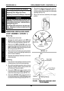
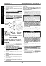
REMOVING/INSTALLING REAR
SHOCK ABSORBERS (FIGURE 8)
Removing
1. Remove the seat. Refer to REMOVING/IN-
STALLING THE SEAT in PROCEDURE 5 of the
Owner’s Manual, part number 1090132.
2. Remove the rear shroud. Refer to
REMOVING/
INSTALLING THE REAR SHROUD in PROCE-
DURE 9 of the Owner’s Manual, part number
1090132.
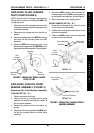
3. Remove the TOP bolt on the right rear shock
absorber.
4. Remove the BOTTOM bolt on the right rear shock
absorber.
5. Slide the right rear shock absorber away from
the rear frame.
6. If necessary, repeat this process for the other rear
shock absorber.
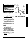
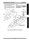
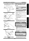
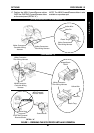
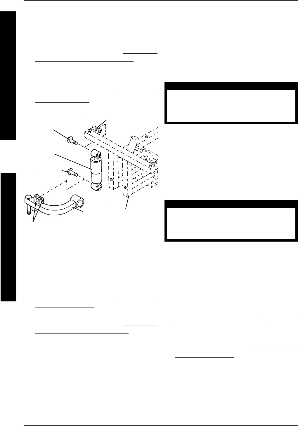
FIGURE 7 - REMOVING/INSTALLING FRONT
SHOCK ABSORBER
Top Bolt
Bottom Bolt
Front Shock
Absorber
Front Frame
Assembly
Tie Rod
Assembly
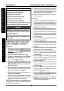
Installing
NOTE: When installing the bolts for the rear shock
absorber, the TOP and BOTTOM bolts should be
facing opposite directions.
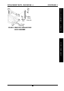
1. Slide the right rear shock absorber onto the rear
frame assembly, aligning the mounting hole in the
BOTTOM of the right rear shock absorber with
the mounting holes in the rear frame assembly.
CAUTION
DO NOT overtighten the bolt securing the
right rear shock absorber to the rearframe
assembly. Otherwise, damage to the right
rear shock absorber may occur.
2. Install one (1) bolt through the BOTTOM mount-
ing hole in the right rear shock absorber and the
BOTTOM mounting holes in the rear frame as-
sembly, making sure the bolt is facing AWAY from
the controller. Torque the hex cap screws between
122 - 148 in./lbs.
3. Align the mounting hole in the TOP of the right
rear shock absorber with the mounting holes in
the rear frame.
CAUTION
DO NOT overtighten the bolt securing the
right rear shock absorber to the rear frame
assembly. Otherwise, damage to the right
rear shock absorber may occur.
4. Install one (1) bolt through the TOP mounting
hole in the right rear shock absorber and the TOP
mounting holes in the rear frame assembly, mak-
ing sure the bolt is facing TOWARD the control-
ler. Torque the hex cap screws between 122 -
148 in./lbs.
5. Repeat this procedure for the other rear shock
absorber.
6. Reinstall the rear shroud. Refer to
REMOVING/
INSTALLING THE REAR SHROUD in PROCE-
DURE 9 of the Owner’s Manual, part number
1090132.
7. Reinstall the seat. Refer to
REMOVING/IN-
STALLING THE SEAT in PROCEDURE 5 of the
Owner’s Manual, part number 1090132.
PROCEDURE 11 REPLACEMENT PARTS - PANTHER MX - 4
P
A
N
T
H
E
R
M
X
4
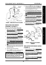
Mounting Holes
Mounting Holes
5. If necessary, repeat this procedure for the other
front shock absorber.
6. Return the front frame assembly to the upright
position.
7. Reinstall the front wheels. Refer to
REMOVING/
INSTALLING THE FRONT WHEELS in PRO-
CEDURE 9 of the Owner’s Manual, part number
1090132.
8. Reassemble the front frame assembly and the
rear frame assembly. Refer to
TRANSPORT-
ING THE SCOOTER in PROCEDURE 10 of the
Owner’s Manual, part number 1090132.