


4242
PROCEDURE 7
C
O
N
T
R
O
L
L
E
R
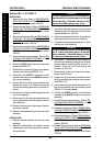
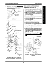
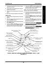
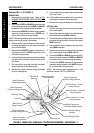
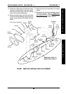
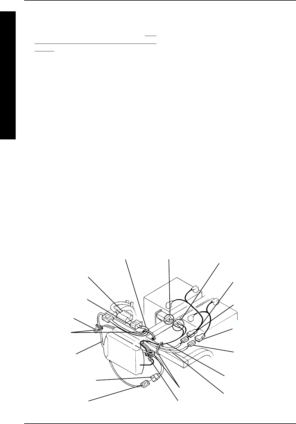
FIGURE 5 - REMOVING/INSTALLING CONTROLLER HARNESSES - PANTHER MX - 4
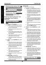
Cable Ties
Retaining Tabs
Cable Tie
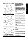
Red Connector - Power
Wiring Harness
Red Connector - Controller
Wiring Harness
Black Connectors -
Controller Wiring Harness
White Connector -
Transaxle Assembly
White Connector -
Controller Wiring Harness
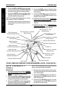
Metal Connectors -
Circuit Breaker
Metal Connectors -
Controller Wiring Harness
White Connector -
Transaxle Assembly
White Connector -
Controller Wiring Harness
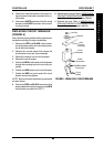
Panther MX - 4 (FIGURE 5)
REMOVING.
1. Disconnect the controller wires. Refer to DIS-
CONNECTING/CONNECTING CONTROLLER
WIRES in this procedure of the manual.
2. Disconnect he RED and BLACK connectors of the
power wiring harnesses from the RED and BLACK
connectors of the controller wiring harnesses.
3. Disconnect the WHITE connector of the transaxle
assembly wiring harness from the WHITE con-
nector of the controller wiring harness.
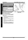
NOTE: Note of the positions of the metal connectors
before removing for proper reinstallation.
4. Disconnect the metal connectors of the control-
ler wiring harnesses from the metal connectors
of the circuit breaker.
5. Disconnect the WHITE connector of the tiller wir-
ing harness from the WHITE connector of the
controller wiring harness
6. Cut the cable tie securing power wiring harnesses
and the metal connector wiring harness to the
rear frame.
7. Cut the cable tie securing the metal connector
wiring harnesses to the retaining tab.
8. Remove the metal connector wiring harnesses
from the retaining tab.
9. Cut the cable tie securing the tiller wiring harness
to the rear frame.
10. Cut the cable tie securing the main control hous-
ing wiring harnesses to the retaining tab.
11. Remove the wiring harnesses from the scooter.
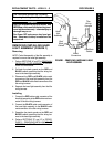
INSTALLING.
1. Position the metal connector wiring harnesses
in the retaining tab.
2. Secure the metal connector wiring harness into
the retaining tab using NEW cable ties.
3. Secure the power wiring harnesses and the metal
connector wiring harness to the rear frame using
NEW cable ties.
4. Secure the tiller wiring harness to the rear frame
using NEW cable ties.
5. Secure the main control housing wiring harnesses
to the retaining tab using a NEW cable tie.
6. Connect the RED and BLACK connectors of the
power wiring harnesses to the RED and BLACK
connectors of the controller wiring harnesses.
7. Connect the WHITE connector of the transaxle
assembly wiring harness to the WHITE connec-
tor of the controller wiring harness.
NOTE: Be sure the metal connectors are in the
positions noted in STEP 2 of REMOVAL.
CONTROLLER
Retaining Tab
Metal Connector Wiring
Harness
Tiller Wiring
Harness
Main Control
Wiring Harness
Black Connectors - Power
Wiring Harness
Power Wiring Harness