


1717
Section D - Disconnecting/Connecting
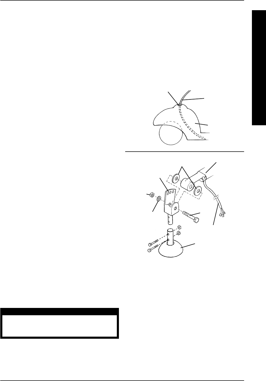
Tiller Assembly And Handle Bar Joint
(FIGURE 7)
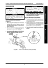
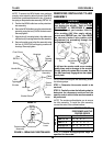
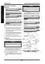
DISCONNECTING.
1. Return the front frame assembly to the upright
position.
2. Remove the bolt, small washer, two (2) large
washers and self-locking nut securing the base
handle bar joint to the tiller assembly.
3. Slowly pull the tiller assembly away from the front
frame assembly until there is no slack left in the
tiller wiring harness (DETAIL “A”).
4. Refer to the chart on page 11 of this manual to
determine which section(s) need to be performed
next to successfully complete the removal/instal-
lation of the tiller assembly.
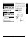
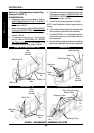
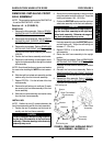
CONNECTING.
NOTE: To simplify this procedure, lay the tiller as-
sembly on the shroud and then align the necessary
components.
1. Align the mounting hole in the tiller assembly with
the holes in the two (2) large washers and with
the mounting holes in the base handle bar joint.
CAUTION
DO NOT overtighten the bolt securing tiller as-
sembly to the base handle bar joint. The tiller
will bind and not work properly.
2. Secure the tiller assembly to the base handle bar
joint using the provided bolt, small washer, and
self-locking nut, making sure the bolt passes
through the two (2) large washers. Torque the
locking nut between 3 - 6 in./lbs.
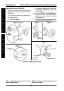
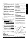
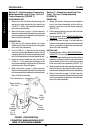
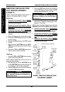
CONNECTING (FIGURE 6).
1. Connect the RED cable metal connector of the
head light assembly to the RED cable metal con-
nector of the tiller wiring harness.
2. Connect the BLACK cable metal connector of
the head light assembly to the BLACK cable
metal connector of the tiller wiring harness.
3. Reposition the plastic guards on the RED and
BLACK cables connecting the tiller wiring har-
ness to the head light assembly.
4. For LYNX LX - 3 ONLY, slowly thread the wires
of the head light assembly through the hole in
the shroud, until most of the wires of the head
light assembly are on the underside of the front
frame assembly.
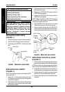
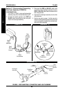
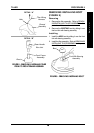
3. Push any remaining slack in the tiller wiring har-
ness through the hole in the shroud, until the wir-
ing harness is on the underside of the front frame
assembly (DETAIL “A”).
4. Flip the front frame assembly onto its side.
5. Refer to the chart on page 11 of this manual to
determine which section(s) need to be performed
next to successfully complete the removal/instal-
lation of the tiller assembly.
PROCEDURE 4TILLER
T
I
L
L
E
R
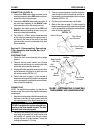
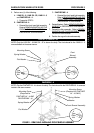
FIGURE 7 - DISCONNECTING/CONNECTING
TILLER ASSEMBLY AND HANDLE BAR JOINT
Tiller Assembly
Base Handle
Bar Joint
Bolt
Small
Washer
Self-
locking
nut
Large
Washers
Tiller Wiring
Harness
Boot
DETAIL “A”
Tiller Wiring
Harness
Hole In Shroud
Front Frame
Assembly