


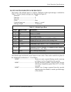
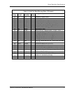

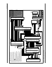


Full Stack Drawing
Apollo GX50/60/65 Installation Manual
75
OBS_C{R Lo}
OBS_D{S1}
OBS_E{S3}
24
7
26
25
Rslvr{H}
Rslvr{C}
Rslvr{D}
Rslvr{E}
Rslvr{F}
Rslvr{G}
MD200-306
NAV+ Valid (Flag)
NAV- Valid (Flag)
+TO (Flag)
+From (Flag)
CDI+ L
CDI+ R
+NAV Flag
-NAV Flag
+TO Flag
+FR Flag
CDI Left
CDI Right
10
29
12
11
14
13
Back Crse
ILS Energize
15
33
BC Ann.
Ann. Pwr - 14V
28V Dimmer*
14V Dimmer
Ground
To Auto-Pilot
High Sense
OBS_F{S4}
OBS_G{S2}
OBS_H{R Hi}
16
34
Ann. Pwr - 28V
NAV Ann.
SL30 #1
GS+ Valid (Flag)
GS- Valid (Flag)
GSI+ Up
GSI+ Down
28
32
30
31
GX50
NAV Valid + (Flag)
NAV Valid - (Flag)
TO+ (Flag)
From+ (Flag)
GS Valid + (Flag)
GS Valid - (Flag)
GSI+ Up
GSI+ Down
22
23
17
16
40
41
34
35
CDI+ L
CDI+ R
28
29
20
21
15
14
38
39
32
33
ACU
26
27
+Vert (GS) Flag
-Vert (GS) Flag
+UP
+DOWN
GPS Ann.
Spare (GPS)
Spare (Nav) 61
62
ILS Energize
HI Sense
57
58
37-Pin Connector
60
Spare
(Common)
VDI+UP
VDI-DN
VDI Valid (+)
GND
ACTIVE
APPRCH
Hold
MSG
Hold Select
PTK
CDI+L
CDI+R
+From
+To
NAV + Valid
RxD2
30
31
28
29
15
33
34
16
26
17
14
13
11
12
10
20
21
Serial GND
36
37
25
12
9
10
13
11
30
31
18
19
42
8
24
VDI+UP
VDI-DN
VDI Valid (+)
VDI/NAV Valid(-)
Active
Approach
OBS/Hold
MSG
GPS/SEQ
PTK
CDI+L
CDI+R
From+
To+
NAV Valid (+)
MX20
Port 1 GND
Port 1 IN
23
4
SL70
RxD
Serial GND
TxD
C4
C2
C1
B4
B2
B1
A4
A2
A1
D4
GND
Gray Code Altitude Input
Altitude Encoder
or Serializer
TX RS232
GND
4
3
5
Altitude
Encoder
or Digitizer
15
34
32
33
12
31
13
35
30
16
14
Only When Using Gray Code Altitude Input
Com 2 Audio Hi
Com Mic 2 Audio Hi
Com 2 Mic Key
SL15
37-Pin Connector
Note 12
Note 12
Note 12
Note 2 Note 2
Note 3
Note 3
Note 5
Note 6
Serial GND
TxD1
Audio Gnd
Nav Audio Out
5
23
20
3
Note 7
Note 11
Note 7
Mic 2
Mic 1
TxKey
Intercom
Select
Speaker
14
13
15
8
7
4
12
6
Headphone
Audio GND
Mic GND
15-Pin Connector
10
H
V
1
9
P
R
12NAV 1 Audio
GND
Note 2
Note 3
Note 8
Note 2
Note 3
1
2
3
6
5
4
12
11
10
9
8
7
22
23
19
18
21
Annunciator
Backlight Dimmer 14 V Systems
Backlight Dimmer 28 V Systems
(GND if 14V)
20
Annunciator Power
24
* Ground for 14V lighting
16
15
14
13
17
+13.8 VDC **
+28 VDC **
**Appropriate Aircraft Bus
Com 1 Audio Hi
Com Mic 1 Audio Hi
Com 1 Mic Key
25-Pin Connector
Power
+
Power GND
1
2
Avionics
Power
+
-
2A
Port 3 GND
Port 3 IN
25
7
Avionics
Power
+
-
Power +
Power Ground
1
2
2A
Avionics
Power
+
-
Power +
Power Ground
1
2
2A
1
9
Power +
Power GND
5A
+
-
78
1
Power (+VDC)
GND
2A
+
-
16
20
Power +
Power GND
5A (14 VDC)
3A (28 VDC)
+
A/C Power
Avionics
Power
Note 10
Note 11
Speaker Hi
Speaker Lo
W
22
Note 3
Sim Select
GND
7
25
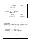
NOTES:
1. This diagram is provided to show the interconnection between UPS AT
units. Full wiring diagrams for each unit are provided in the appropriate
installation manuals. Refer to all documentation to ensure successful
installation.
2. Connect cable shields to the mounting frame: pigtails < 1.25 inches.
3. Connect shields to chassis ground at both ends of each shielded cable.
4. Reference the ACU installation manual if installing NAV/GPS source
selector.
5. ILS and spare annunciator relays are only available in the Mod A ACU.
6. Terminate shield to within 2 inches of connector. Heat shrink over edges.
7. Either a serial or parallel altitude encoder may be installed. A serial
version is the perferred option. In this diagram, the parallel installation
is identified by .
8. The audio ground and mic ground connections may use a common point
on the audio panel.
9. Not all audio panel connections are shown on this drawing due to the
variances in installations. Consult the SL15 installation manual.
10. If the installation is utilizing gray code altitude input and the SL70 is being
used as a serializer, do not install the altitude encoder or serializer shown.
11. Altitude encoders are not UPS Aviation Technologies-provided equipment.
Refer to the appropriate encoder installation manual to ensure proper
power and signal connections.
12. Use shielded cable for Resolver signals.
13. Simulator mode if left open. Connect pin 7 to ground for normal operation.
14. SL30 #1 - Interfaces to the GX50 to obtain distance, speed, and time for the
tuned Navaid. Interfaces and displays data on the MX20.
SL30 #2 -The DST (distance, speed, time) display must be disabled
(available in SW Ver 1.2, and later) to prevent misleading DST data.
15. Use caution when adding RS-232 devices. Fan-out should not be more than three
devices. The MX20 Port 3 output can be used to echo Nav/Comm remote frequency
data that is transmitted from the GX, which reduces the GX fan-out. However, the
MX20 must be operating before the echoed data can pass through the MX20.
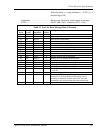
37-Pin Connector
OBS_C{R Lo}
OBS_D{S1}
OBS_E{S3}
24
7
26
25
NAV+ Valid (Flag)
NAV- Valid (Flag)
+TO (Flag)
+From (Flag)
CDI+ L
CDI+ R
10
29
12
11
14
13
Back Crse
ILS Energize
15
33
OBS_F{S4}
OBS_G{S2}
OBS_H{R Hi}
16
34
SL30 #2
GS+ Valid (Flag)
GS- Valid (Flag)
GSI+ Up
GSI+ Down
28
32
30
31
Note 1
Note 1
Note 1
Note 2
Note 3
Audio Gnd
Nav Audio Out 23
20
Mic 2
Mic 1
TxKey
Intercom
Select
Speaker
14
13
15
8
7
4
12
6
Headphone
Audio GND
Mic GND
15-Pin
Connector
Note 2
Note 3
Note 8
Note 2
Note 3
Avionics
Power
+
-
Power +
Power Ground
1
2
2A
Rslvr{H}
Rslvr{C}
Rslvr{D}
Rslvr{E}
Rslvr{F}
Rslvr{G}
MD200-306
+NAV Flag
-NAV Flag
+TO Flag
+FR Flag
CDI Left
CDI Right
BC Ann.
Ann. Pwr - 14V
28V Dimmer
*
14V Dimmer
Ground
Ann. Pwr - 28V
NAV Ann.
+Vert (GS) Flag
-Vert (GS) Flag
+UP
+DOWN
GPS Ann.
Note 2
Note 3
1
2
3
6
5
4
12
11
10
9
8
7
22
23
19
18
21
Backlight Dimmer 14 V Systems
20
24
* Ground for 14V lighting
16
15
14
13
17
**Appropriate Aircraft Bus
25-Pin
Connector
1
9
Power +
Power GND
5A
+
-
Avionics
Power
Bottom Connector J1
Note 8
Note 9
20
2A (14 VDC)
3A (28 VDC)
11-33 VDC
Power
Annunciator
+13.8 VDC **
Annunciator Power+28 VDC **
Backlight Dimmer 28 V Systems
(GND if 14V)
NAV 2 Audio 13
RxD1 4
RxD1
4
Serial GND
3
TxD1 5
Serial GND 3
Note 13
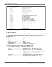
Typical Full Stack Interconnection
Diagram with Two SL30s
9/18/03SCH 0103
Drawing No. Revision Revision Date
E
2345 Turner Rd, SE
Salem, OR 97302
Phone: 503-581-8101
www.garminat.com
Rev Rev Date Reference
--
A 4/16/01
Serial port change to support new SL30 Interface and
GPS roll steering output.
Initial distribution
TxD2 22
Roll Steering
Output
RxD1 4
5/8/01
Wiring and note changes for GX-SL30 interface
pursuant to SL30 SW Ver 1.2
Port 3 OUT
Note 15
B
6
2 Power GND
-
1 Power +
C
4/19/02
Added Heater power and ground wire connections
for the MX20
D
9/4/02
Changed MX20 fuse to circuit breaker and its
current rating
9/18/03E Company name change.
Figure 21 - Full Stack Interconnect Drawing