


Installation
16 Apollo GX50/60/65 Installation Manual
GPS ANTENNA
The mounting location and cable connections for the GPS antenna are very important. The
antenna should be mounted no closer than two feet from VHF comm transmitter antennas, six
inches from other antennas emitting less than 25 watts, and two feet from higher power
antennas. Special care should be taken to ensure that the GPS antenna is not mounted in close
proximity to antennas that may emit harmonic interference at the L1 frequency of
1575.42 MHz. Refer to the antenna installation manual for installation instructions.
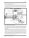
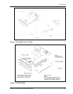
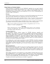
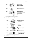
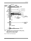
The connectors are included in the installation kit, and are intended for use with RG-142B size
coax cable. If using a different diameter coax, alternative connectors may be required. Assembly
instructions for the connectors are included in Figure 6 and Figure 7. RG-142B cable can be used
as long as the length is less than 20 feet. For longer lengths, use a low loss 50Ω coax.
Suggestion: Temporarily locate the GPS antenna with coax connected to the GX50/60/65 and
check the GPS performance as described in the GPS Operation and Position test in the Post
Installation Checkout on page 27. Once a suitable location has been verified, then
permanently mount the antenna.
Note: If using a GPS antenna that was already on the aircraft, or if mounting the antenna
closer than two feet from a comm antenna, conduct the GPS Operation and Position test in
the Post Installation Checkout on page 27. If the GX50/60/65 passes the test, then moving the
antenna is not necessary.
Once the antenna mounting position has been prepared, route the coax cable from the antenna
to the GX50/60/65. Proper selection of coax cable and assembly of connectors is critical to
GPS signal performance. The cable loss from the antenna to the GX50/60/65 should be
limited to a maximum of 4 dB. Minimize the coax length for optimum performance and DO
NOT coil excess cable. Leave only enough for service loops. The coaxial connectors and
adapters, such as TNC to BNC, add additional loss to the cable and should be considered
when computing the maximum 4 dB loss. A typical loss of 0.2 dB can be used for each
connection. The typical cable loss for 20 feet of RG-142B coax with a connector on each end
is 4 dB.
During the post-installation checkout, susceptibility to harmonics of VHF comm transmitters
will be evaluated. If problems arise, then better isolation, or distance, may be required
between the GPS and comm antennas, or a notch filter may be installed in series with the
antenna coax of the VHF comm transceiver to reduce or eliminate the harmonic interference.
A notch filter for this use (part #162-1059) is available from Garmin AT.
Note: GX60/65 performance has been verified in typical installations and has not shown
problems with the built-in comm interfering with the GPS when installed according to
the recommended installation guidelines.
If a VHF comm transmitter causes problems with the GPS on the selected frequencies as
listed in the post-installation checkout, the problem may be due to the ELT. This can be
verified by disconnecting the ELT antenna coax at the ELT unit. If the ELT is found to cause
the problem, then contact the ELT manufacturer or replace the ELT.