


Introduction
Apollo GX50/60/65 Installation Manual
5
• an altitude encoder/converter
• Fuel/Airdata Computer (e.g. Shadin Model ADC-200)
When the GX50/60/65 is installed for VFR, a placard stating “GPS Limited to VFR Use
Only” or an FAA approved equivalent statement must be placed next to the primary indicator.
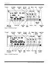
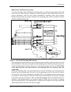
IFR GPS NAVIGATION INSTALLATION
When installed for IFR operation, the GX50/60/65 requires connections to several external
indicators. The minimum connections for IFR operation are as follows.
• an A-33 or A-34 GPS antenna
• power input
• an external non-numeric indicator, such as a CDI or HSI
• external lamp annunciators including “MSG” and “PTK”
For TSO-C129a A1 (non-precision approach) operation the following connections are also
required (GX65 not included):
• external lamp annunciators including “APPRCH” and “ACTIVE”
• an “OBS/HLD” external annunciator (with switch)
• altitude input from an altitude encoder/converter or air data computer
The GX50/60/65 can also be connected to other external devices such as:
• an autopilot
• a moving map display connected to an RS-232 serial output
• an SL40 VHF Comm radio connected to an RS-232 serial output (For GX50 units)
• Fuel/Airdata Computer (e.g. Shadin Model ADC-200)
COMM TRANSCEIVER - GX60/65
For standalone installations, the comm requires connections to:
• a standard comm antenna
• a microphone (or microphones)
• a speaker or headphone
• power input
The microphone and speaker or headphones may be installed dedicated to the GX60/65
comm, or by connection to an audio panel.
The comm installation can also include optional connections:
• external remote flip-flop button
DATABASE UPDATES
The GX50/60/65 utilizes a Flybrary database stored on a standard plug-in memory card for
easy updating and replacement. Simply plug in the new datacard to update your existing
database or change to a new database.
Contact the Garmin AT factory for information on databases available for the GX50/60/65.