


The NiCad battery charger circuit is built around the Integrated Circuit Systems, Inc. ICS1700A rapid
charge controller. This controller uses a pulsed charging system, which is in effect when external power
is supplied through the rear connector. When the unit is off, the batteries are not being charged by the
external supply. When the unit is connected to a wall charger, however, the batteries are trickle charged
at a constant current of 125 mA.
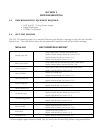
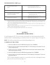
1.2.3 RF/IF Assembly
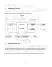
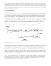
The RF/IF assembly consists of a dual conversion receiver, a frequency synthesizer, and a high precision
crystal oscillator. The receiver consists of a ceramic RF filter, RF and IF amplifiers, mixers, and an IF fil-
ter. The frequency synthesizer uses the high precision oscillator as a reference frequency for the phase
detector in the synthesizer. The resultant frequency is used in the mixer section to produce the first IF.
After further amplification and mixing with a product of the crystal oscillator, the baseband IF is passed
to the CPU Board for processing. The crystal output is also used for the system clock pulse. The RF/IF
assembly is contained within a shielding fence/cover and connection to the antenna is made via a BNC
connector. The RF/IF supplies +5 volts to the antenna’s preamplifier through this BNC connector.
The block diagram in Figure 4 below shows the interaction between components on the RF/IF Assembly.
Figure 4
RF/IF Block Diagram
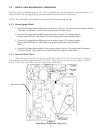
1.2.4 Interface Board and Data Cards
The Interface Board provides two-way data transfer capability between the Main Board and a data card.
NavData® cards, available in sizes from 1 to 4 megabytes depending on the content/coverage area,
allow for data transfer to the Main Board only. User data cards, with 768 kilobytes of flash memory
data storage, may be used to save user data/settings from the GPS 155 or restore that information to
the GPS 155. Address and data lines from the Main Board route through the Interface Board’s output
buffers to the data card. A plastic race secures the Interface Board at the front of the unit and serves to
guide the data card onto the 40-pin connector.
NOTE: When servicing the GPS 155, user-defined waypoints, routes, settings, etc., may be saved on a
user data card (010-10032-03) first. In the event these data are lost, they may then be restored from
the user data card before the unit is returned to service. Refer to Appendix A of the GPS 155 Pilot’s
Guide for additional information on user data card operation.
5