


3.2.8 Rotary Switch Assembly (011-CS033-00) Removal
1. Remove the covers as described in Section 3.1
2. Remove the Control/Display Unit as described in Section 3.2.1
3. Remove the two rotary switch knobs by loosening the two M3 x 4mm set screws on the inner knob (430-00002-
00). After removing the inner knob, gently pull the outer knob off of the rotary switch shaft.
4. Disconnect the rotary switch wiring harness from the connector on the Display Board.
5. Remove the hex nut securing the rotary switch to the Control/Display Unit. This nut is 1/2” and may be removed
with a deep 12-point socket.
3.2.9 Display Board (012-00029-00) Removal
1. Remove the covers as described in Section 3.1.
2. Remove the Control/Display Unit as described in Section 3.2.1.
3. Disconnect the rotary switch wiring harness from the connector on the Display Board.
4. Remove the four M2.3 x 6mm screws (211-00028-00) that secure the Display Board to the CDU bezel.
5. Carefully pull the Display Board away from the CDU bezel, disengaging it from the Keypad Board connector.
(NOTE: Retain the four rubber grommets [252-00005-00] for later reassembly.)
3.3 REASSEMBLING THE UNIT
1. Attach the power/dimmer switch to the chassis by reversing the steps followed in Section 3.2.7. The switch is
correctly installed when the contacts and flexible circuit cable are pointed away from the chassis frame.
2. Ensure that the power/dimmer switch is in the “off” position
3. Slide the battery pack connector (P800) and cable into the cutout in the chassis.
4. Mount the battery pack to the chassis using three M3 x 5mm screws (211-50227-05).
5. Attach the RF/IF Assembly to the Main Board by reversing the steps followed in Section 3.2.5.
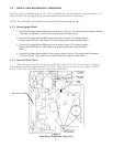
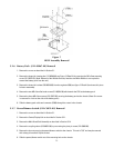
6. Mount the Main Board Sub-Assembly on the chassis by reversing the steps followed in Section 3.2.4. Be sure
to pull up on the retaining lip of the ZIF connector (J804) before inserting the flexible circuit cable. Also, ensure
that the heat sink insulator (250-00016-00) is installed on regulator I800 before installing the heat sink clamping bar
(see Figure 12 - Detail A).
7. Mount the Interface Board to the chassis by reversing the steps followed in Section 3.2.3.
8. Install the Altitude Decoder Board by reversing the steps followed in Section 3.2.2. Carefully observe proper
orientation and alignment when reconnecting the ribbon cable to the board. Do not connect the battery pack
wiring harness to the Main Board until the Control/Display Unit is installed.
9. Mount the Display Board to the CDU bezel by reversing the steps followed in Section 3.2.9. Be sure to reinstall
the four rubber grommets before mounting the board.
10. Mount the Rotary Switch Assembly to the Control/Display Unit by reversing the steps followed in Section 3.2.8.
The switch is correctly installed when the wiring harness points toward the top of the unit. Torque hex nut to
25±3 in oz.
15