


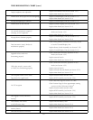


TROUBLESHOOTING CHART (cont.)
Unit does not detect external Check external power connection
power
4
Replace Main Board (see Section 3.2.4)
No serial data output Replace Main Board (see Section 3.2.4)
No external CDI output or external
Check connections and verify operation in Test
CDI functions improperly
Mode (see Section 4.3.2)
Replace Main Board (see Section 3.2.4)
Invalid characters displayed
Replace ROM (see Section 4.2)
Replace Main Board (see Section 3.2.4)
1
If UTC Time is incorrect, unit may be reset by holding the CLR key down while turning the unit on. The unit must then be
attached to an antenna, allowed to search the sky and collect new almanac data. This process may take 20-30 minutes. CAU-
TION: All user waypoints/settings will be lost if the unit is reset.
2
The GPS 155 will eventually perform an AutoLocate™ and lock onto satellites, however this can add an additional 10-15 min-
utes to the normal lock-on time.
3
Display of low velocity numbers when not moving can occur when the unit is in 2D mode and should not be considered a
problem. However, this should seldom occur in 3D mode.
4
The “Turning Off” message appears at/below approximately 9 VDC external power.
SECTION 3
DISASSEMBLY INSTRUCTIONS
To avoid damaging the GPS 155’s circuit boards and assemblies, the following procedures should be
carefully followed. Assembly drawings are included in Section 5 for reference (Figures 12 through 15).
NOTE: The NavData card should be removed before disassembling the unit.
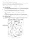
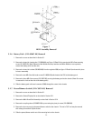
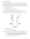
3.1 REMOVAL OF THE COVERS
1. Remove the two M3 x 5mm screws (211-50227-05) retaining the top cover (115-00037-00).
2. Remove the top cover by sliding it rearward approximately 1/4” until the retaining lip is fully exposed. The cover
can then be lifted off the unit.
3. Carefully turn the unit over. CAUTION: The GPS 155 contains numerous static-sensitive components. Always
observe proper anti-static precautions.
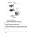
4. Remove the two M3 x 5mm screws (211-50227-05) retaining the bottom cover (115-00038-00).
5. Remove the bottom cover by sliding it rearward about 1/4” until the retaining lip is fully exposed. The cover can
then be lifted off the unit.
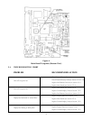
NOTE: If further disassembly is required, it is a good idea (at this time) to disengage the battery
pack wire from the main board (see figure 12).
11