


2.3 INITIAL TROUBLESHOOTING OPERATIONS
The first step in troubleshooting the GPS 155 is to remove the top and bottom covers (see Section 3.1).
Verify that the unit is being properly powered and the internal clock is functional.
NOTE: The NavData® card should be removed before disassembling the unit.
2.3.1 Power Supply Check
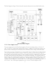
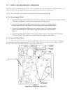
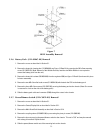
1. Check the DC voltage between D805 and ground as shown in Figure 5. The voltage should be between -9.60 and
-14.40 volts. If the voltage is out of the limits specified, replace the Main Board.
2. Check the DC voltage between L800 and ground as shown in Figure 5. The voltage should be
between 4.8 and 5.2 volts. If the voltage is out of the limits specified, replace the Main Board.
3. Check the DC voltage between D804 and ground as shown in Figure 5. The voltage should be
between 48.00 and 72.00 volts. If the voltage is out of the limits specified, replace the Main
Board.
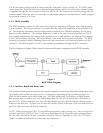
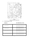
4. Check the DC voltage between I806 pin 1 and ground as shown in Figure 6. The voltage should be between
11.75 and 12.25 volts. If the voltage is out of the limits specified, replace the Main Board.
2.3.2 Internal Clock Check
Check the clock speed by placing an oscilloscope probe at I112 pin 25 as shown in Figure 6.
The frequency should be approximately 16.4 MHz. If the clock is not operational, replace the RF/IF
Board. If the clock still fails to function, replace the Main Board.
Figure 5
Main Board Testpoints (Top View)
8
Rear Connector