


3.2.4 Main Board Sub-Assembly Removal
The Main Board Sub-Assembly consists of the Main Board (012-00089-00) and the RF/IF Assembly
(012-00091-00). If required, this sub-assembly may be further dismantled by following the steps in
Section 3.2.5.
1. Remove the covers as described in Section 3.1.
2. Remove the Control/Display Unit as described in Section 3.2.1.
3. Remove the Altitude Decoder Board as described in Section 3.2.2.
4. Remove the hex nut securing the BNC connector to the chassis. This nut is 9/16” and may be removed with a
deep 12-point socket.
5. Pull the BNC connector out of its cutout on the chassis.
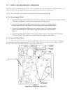
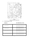
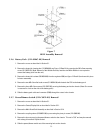
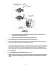
6. Remove the heat sink clamping bar (115-00049-00, see Figure 12 - Detail A) by removing the M3 x 5mm mounting
screw (211-50227-05).
7. Remove the heat sink insulator (250-00016-00) from regulator I800 (see Figure 12 - Detail A) and save this piece
for later reassembly.
8. Carefully turn the unit over.
9. The power/dimmer switch uses a flexible circuit cable for connection to the Main Board. This flexible circuit
cable is inserted into a ZIF connector (J804). Pull up on the retaining lip of the ZIF connector. Gently pull the
flexible circuit cable out of the ZIF connector. Take care not to crease the flexible circuit cable.
10. Remove the two #4-40 standoffs (211-63204-08) which hold the 37-pin DSUB connector to the chassis.
11. Remove the M3 x 5mm screw (211-50227-05) and the M3 x 10mm screw (211-50227-15) holding the Main Board to
the chassis.
12. Carefully slide the Main Board upward; pulling it away from the power/dimmer switch and the Interface Board
Connector (J702).
3.2.5 RF/IF Assembly (012-00091-00) Removal
1. Remove the covers as described in Section 3.1.
2. Remove the Altitude Decoder Board as described in Section 3.2.2.
3. Remove the hex nut securing the BNC connector to the chassis. This nut is 9/16” and may be removed with a
deep 12-point socket.
4. Pull the BNC connector out of its cutout on the chassis.
5. Remove the four screws (211-50202-15) and spacers (233-00012-00) which secure the RF/IF Assembly to the
Main Board.
6. Carefully pull the RF/IF Assembly upward, disengaging it from the Main Board Connector (J803). (NOTE: With the
mounting screws removed, the cover for the RF/IF Assembly will be loose. Grip the RF/IF Assembly firmly by the
sides, instead of by its cover, when lifting upward.)
13